Label paper cutting equipment

A technology of cutting equipment and label paper, applied in metal processing and other directions, can solve the problems of complicated operation process, complicated rotation process of rotating parts, and large labor consumption, etc., to achieve the effect of convenient operation and labor saving.

Inactive Publication Date: 2020-08-28
廖裕兴
View PDF6 Cites 16 Cited by
  • Summary
  • Abstract
  • Description
  • Claims
  • Application Information

AI Technical Summary

Problems solved by technology

[0004] In order to overcome the cumbersome process for the staff to control the rotation of the rotating parts, and at the same time, it takes a lot of effort for the staff to swing the tool, and the operation process is cumbersome. The technical problem to be solved is to provide an automatic feeding and cutting machine. Label paper cutting equipment

Method used


Image

  • Label paper cutting equipment
  • Label paper cutting equipment
  • Label paper cutting equipment

Examples


Embodiment 1

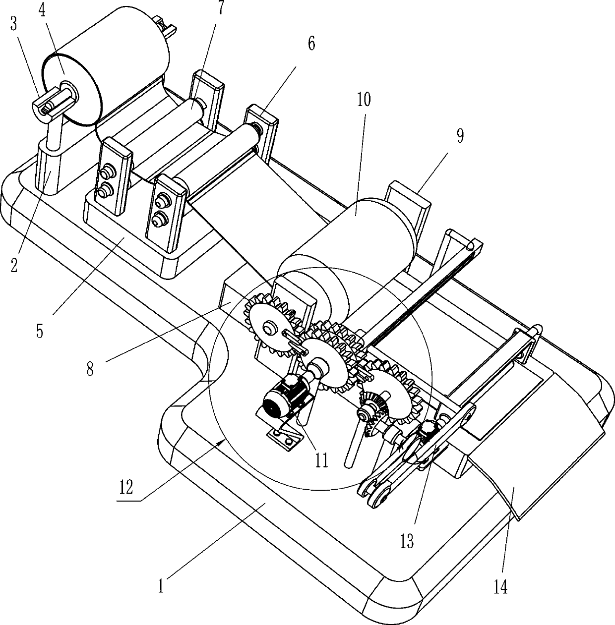
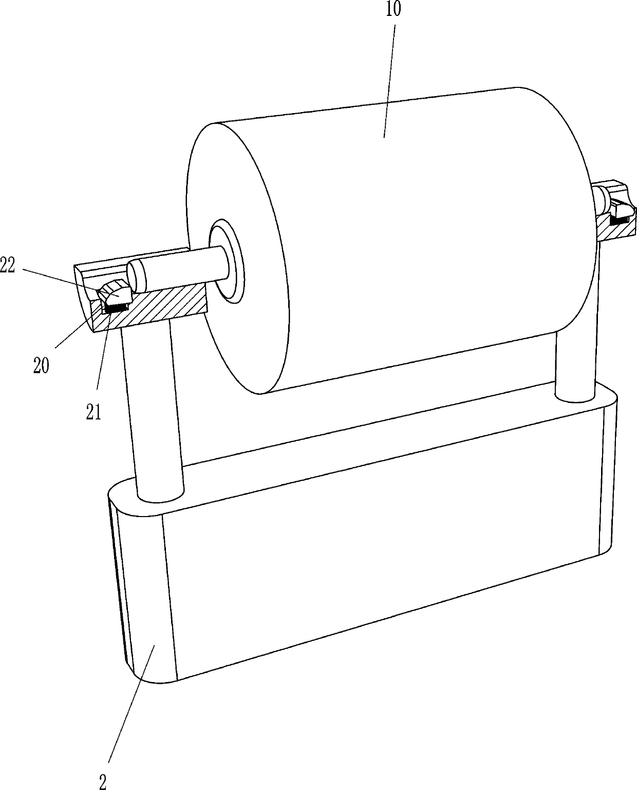
[0022] like Figure 1-5 As shown, a label paper cutting equipment includes a bottom plate 1, a fixed seat 2, a half-ring placement block 3, a roll material drum 4, a mounting seat 5, a mounting frame 6, a transmission roller 7, a workbench 8, and a first bearing seat 9. Rolling cylinder 10, servo motor 11, intermittent transmission mechanism 12 and cutting mechanism 13, the top left side of the bottom plate 1 is provided with a fixed seat 2 and a mounting seat 5, the mounting seat 5 is located on the right side of the fixed seat 2, and the front and back of the fixed seat 2 are symmetrical A half-ring placement block 3 is provided, and the two half-ring placement blocks 3 are used to place the roll material cylinder 4. Two mounting frames 6 are symmetrically arranged on the front and rear sides of the top of the mounting seat 5, and the mounting frames 6 on the front and rear sides are all rotatable. Two drive rollers 7 are provided, a workbench 8 is provided on the top right ...

Embodiment 2

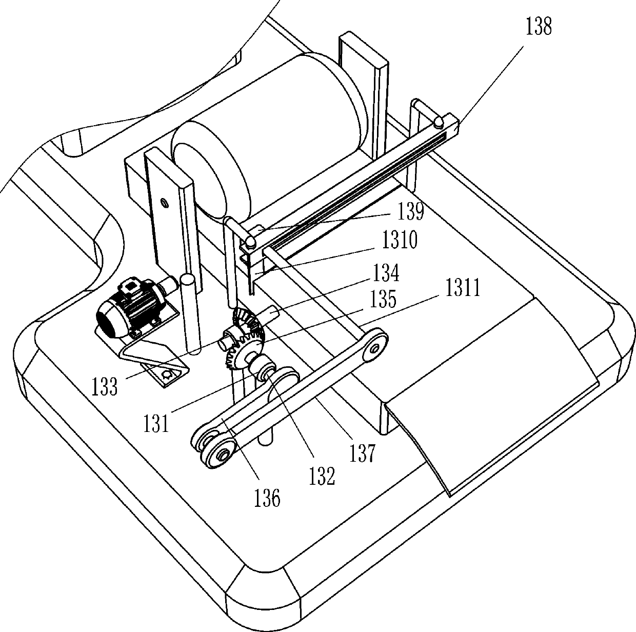
[0027] On the basis of Example 1, such as Figure 1-5 As shown, it also includes a slide plate 14, an N-shaped frame 15, a rotating shaft 16, a rolling roller 17, a rotating motor 18 and a button 19, the right side of the workbench 8 is provided with a slide plate 14, and the right side of the bottom plate 1 is provided with an N-shaped frame 15 , the N-shaped frame 15 is located directly above the workbench 8, the N-shaped frame 15 is rotatably provided with a rotating shaft 16, the rotating shaft 16 is provided with a rolling roller 17, and the right part of the front side of the bottom plate 1 is provided with a rotating motor 18, and the rotating motor 18 The output shaft and the front end of the rotating shaft 16 are connected by coupling transmission, and the front and rear sides in the slide rail 138 are all provided with buttons 19, and the buttons 19 are connected with the rotary motor 18 by lines. When the slider 139 drives the cutting knife 1310 to move backward to ...


PUM


Abstract

The invention relates to cutting equipment, in particular to label paper cutting equipment. The technical problem to be solved is to provide the label paper cutting equipment capable of automaticallyreleasing materials and automatically cutting. According to the technical scheme, the label paper cutting equipment comprises a bottom plate, a material rolling barrel, a mounting seat, a workbench, first bearing seats, a servo motor and an intermittent transmission mechanism, a fixing seat is arranged on the bottom plate, semi-ring placement blocks are symmetrically arranged on the fixing seat, the two semi-ring placement blocks are used for allowing the material rolling barrel to be placed, two mounting frames are symmetrically arranged on the bottom plate, two transmission rollers are rotationally arranged on the mounting frames at the same horizontal positions, the workbench is arranged on the other side of the bottom plate, the bottom plate is symmetrically provided with the first bearing seats with respect to the workbench, a rolling barrel is arranged between the two first bearing seats, and the servo motor is arranged at the position, close to the middle of the workbench, of the bottom plate. According to the label paper cutting equipment, the effects of automatic material releasing and automatic cutting are achieved.

Description

technical field [0001] The invention relates to a cutting device, in particular to a label paper cutting device. Background technique [0002] Label paper can be seen everywhere in life now, and label paper is generally produced in large quantities in rolls. Before the staff needs to use the label paper, they usually use a knife to cut the label paper. The staff first puts a roll of label paper on the rotating part, and then controls the rotation of the rotating part. The rotation of the rotating part will drive the label paper to rotate, and then release the label paper so that the staff can cut the label paper. The staff swings the knife left and right, The cutter swings to the right to cut the label paper. When the cutter swings to the right and is far away from the right end of the label paper, the staff needs to lift the cutter up to temporarily avoid contact with the label paper, and then the staff needs to swing the cutter to the left to make the cutter Move left to ...

Claims


Application Information

Patent Timeline
Patent Type & Authority Applications(China)
IPC IPC(8): B26D1/06B26D5/14B26D7/02B26D7/06B26D7/32
CPCB26D1/065B26D5/14B26D7/025B26D7/06B26D7/32
Inventor 廖裕兴
Owner 廖裕兴
Why Eureka
Try Eureka