
Installation method of large crane beam

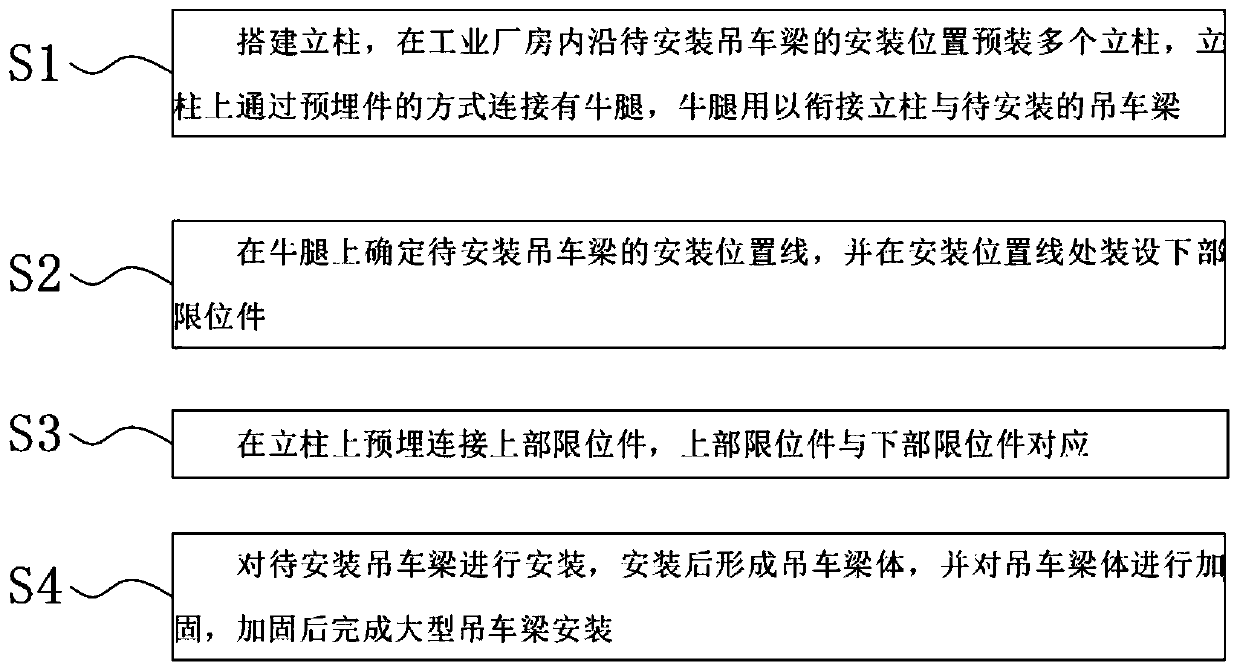
An installation method and crane beam technology are applied to the installation field of large crane beams, which can solve the problems of low installation accuracy and poor strength performance of crane beams, and achieve the effects of avoiding stress, deformation and fracture, reducing construction costs and ensuring position accuracy.

Inactive Publication Date: 2020-08-28
ZHONGCHUAN NO 9 DESIGN & RES INST
View PDF13 Cites 2 Cited by
  • Summary
  • Abstract
  • Description
  • Claims
  • Application Information

AI Technical Summary

Problems solved by technology

The installation accuracy of the crane girder in the prior art is low, and the strength performance of the installed crane girder is poor at the same time

Method used


Image

  • Installation method of large crane beam
  • Installation method of large crane beam
  • Installation method of large crane beam

Examples


Embodiment Construction

[0023] The following will clearly and completely describe the technical solutions in the embodiments of the present invention with reference to the accompanying drawings in the embodiments of the present invention. Obviously, the described embodiments are only some, not all, embodiments of the present invention. Based on the embodiments of the present invention, all other embodiments obtained by persons of ordinary skill in the art without making creative efforts belong to the protection scope of the present invention.

[0024] In the description of the present invention, it should be noted that the orientation or positional relationship indicated by the terms "vertical", "upper", "lower", "horizontal" etc. is based on the orientation or positional relationship shown in the drawings, and is only In order to facilitate the description of the present invention and simplify the description, it does not indicate or imply that the device or element referred to must have a specific o...


PUM


Abstract

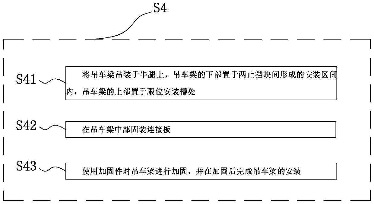
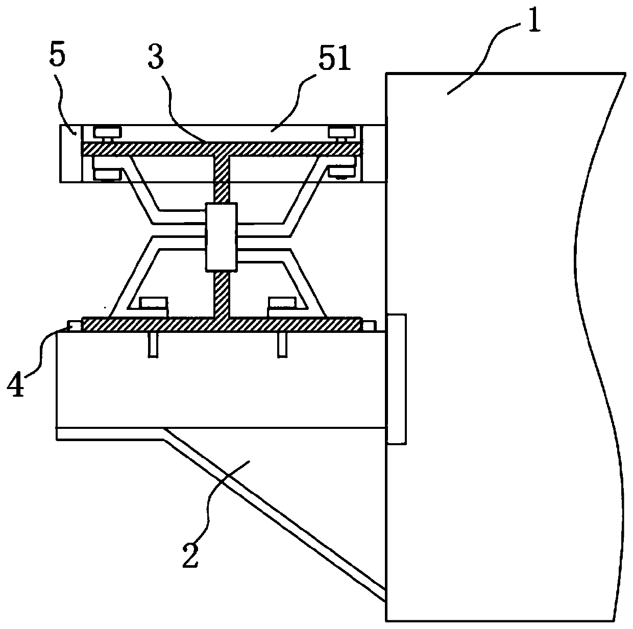
The invention belongs to the field of crane equipment, and particularly relates to an installation method of a large crane beam. The installation method of the large crane beam includes the followingsteps that a plurality of stand columns are established, the stand columns are preloaded along the installation position of crane beams to be installed in an industrial factory building, corbels are connected to the stand columns by the way of embedded parts, and the corbels are used for connecting the stand columns with the crane beams to be installed; installation position lines of the crane beams to be installed are determined on the corbels, and lower part limit members are arranged at the installation position lines; upper part limit members are pre-buried and connected to the stand columns, and the upper part limit members correspond to the lower part limit members; the crane beams to be installed are installed, a crane beam body is formed after installation, the crane beam body is strengthened, and the large crane beam is installed after reinforcement. The installation method of the large crane beam can ensure the position of the crane beams to the installation position, the position accuracy of the crane beams to be installed is ensured, the crane beams are limited through the lower part limit members and the upper part limit members, the stability of the crane beams to beinstalled is ensured, and the pressure resistance of the crane beams is improved.

Description

technical field [0001] The invention relates to the field of crane equipment, in particular to a method for installing a large crane beam. Background technique [0002] The bridge crane is a lifting device that is horizontally placed over the workshop, warehouse and stockyard for material lifting. Because its two ends are located on tall concrete pillars or metal supports, it is shaped like a bridge. The bridge frame of the bridge crane runs longitudinally along the tracks laid on the elevated sides on both sides, which can make full use of the space under the bridge frame to lift materials without being hindered by ground equipment. In industrial plants, overhead cranes are the most widely used due to their large capacity coverage and wide range of services. For steel structure workshops, when the span of the crane girder is ≤9m and the lifting capacity of the crane is ≤20t, the crane girder can be selected according to the national standard atlas with a suitable cross-se...

Claims


Application Information

Patent Timeline
IPC IPC(8): B66C6/00B66C13/00
CPCB66C6/00B66C13/00
Inventor 蒋瓅瞿革蒋斌李玮张晶陈喆李庆武
Owner ZHONGCHUAN NO 9 DESIGN & RES INST
Learn More