Machine head structure of cylinder fabric joining machine

A technology of cloth splicing machine and machine head, which is applied in the direction of cloth feeding mechanism, sewing machine components, program-controlled sewing machines, etc., can solve the problems of unstable product qualification rate, increase the work intensity of workers, reduce the work efficiency of workers, etc., and achieve savings. Manpower, realize automatic operation, avoid the effect of manual handling

Active Publication Date: 2020-08-28
SHAOXING LIANKE MACHINERY
View PDF5 Cites 5 Cited by
  • Summary
  • Abstract
  • Description
  • Claims
  • Application Information

AI Technical Summary

Problems solved by technology

[0002] When the fabrics are connected between the cloth tubes, the replacement of the cloth tubes is generally carried out by manual handling. This operation increases the work intensity of the workers, which will reduce the work efficiency of the workers. The original cylindrical tubular fabric in the workshop Using manual sewing, due to the structural characteristics of the cylindrical cloth, during the sewing process, the workers often have poor seams, uneven seams, large and small seams, and even off-line phenomena. The product is qualified. long-term instability

Method used


Image

  • Machine head structure of cylinder fabric joining machine
  • Machine head structure of cylinder fabric joining machine
  • Machine head structure of cylinder fabric joining machine

Examples


Embodiment

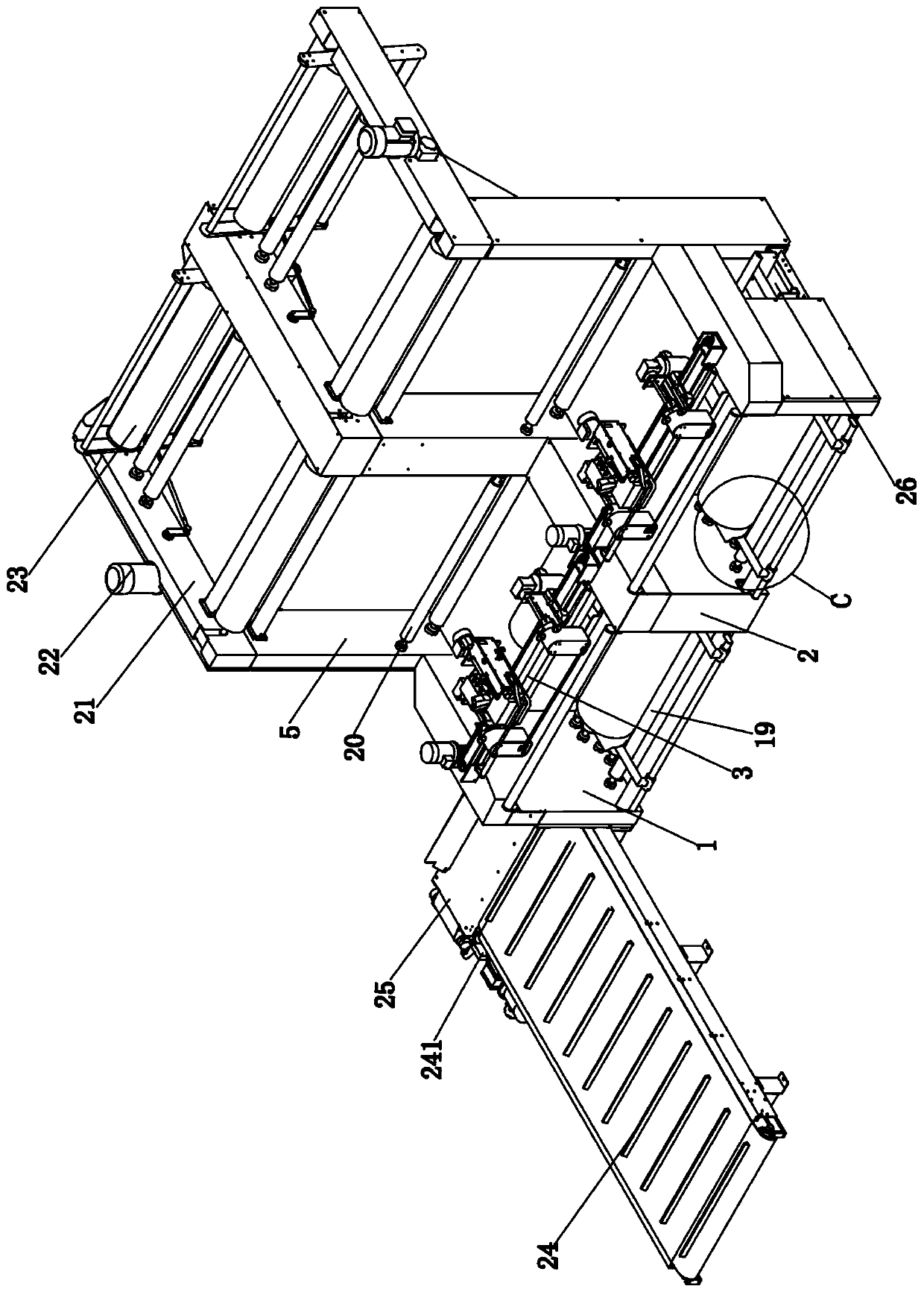
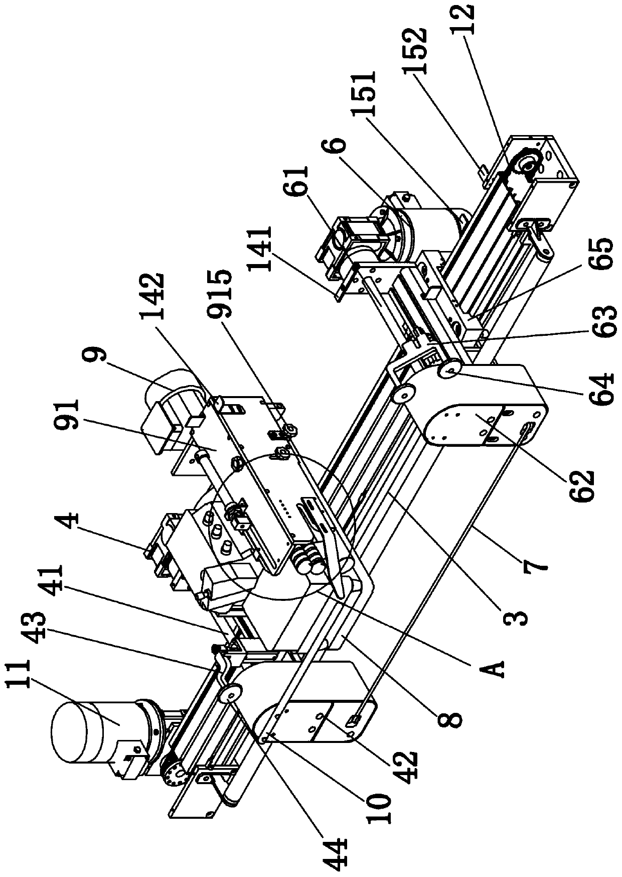
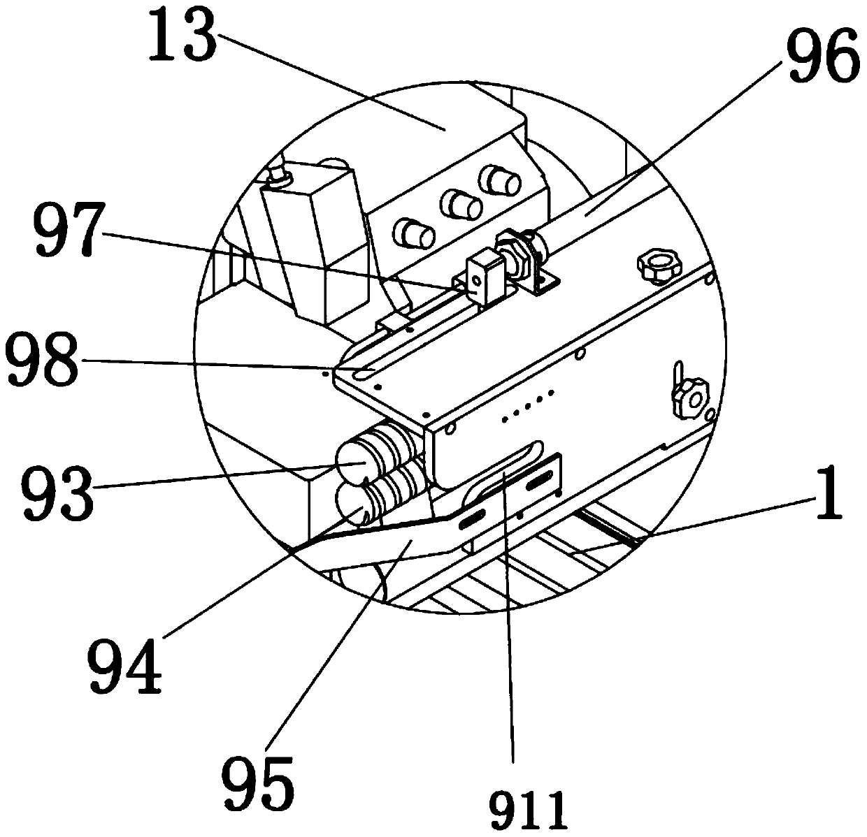
[0024] Embodiment: a kind of machine head structure of cylinder cloth splicing machine, as Figure 1-Figure 9Shown, comprise front vehicle frame 1 and rear vehicle frame 5, rear vehicle frame 5 is fixedly connected on the top of front vehicle frame 1 rear end, the left side of front vehicle frame 1 is provided with storage cloth conveyor belt 24, and the cloth storage conveyor belt 24 The rear end is provided with a cloth feeding conveyor belt 25, and the cloth storage conveyor belt 24 is provided with a first sensor 241 near one end of the cloth feeding conveyor belt 25, and two groups of cloth turning conveying mechanisms 26 are arranged on the rear side of the bottom of the front frame 1. The front side of the middle part of the cloth turning conveyor mechanism 26 is provided with a pneumatic pushing device 261, the right end of the cloth feeding conveyor belt 25 is connected with the cloth turning conveying mechanism 26, and the right end top of the cloth feeding conveyor b...


PUM


Abstract

The invention relates to a machine head structure of a cylinder fabric joining machine and belongs to the technical field of textile equipment. The machine head structure comprises a front frame and arear frame; the rear frame is fixedly connected above the rear end of the front frame; a fabric storage conveying belt is arranged on the left side of the front frame; a fabric feeding conveying beltis arranged at the rear end of the fabric storage conveying belt; and a first sensor is arranged at the top of the end, close to the fabric feeding conveying belt, of the fabric storage conveying belt. According to the machine head structure, two groups of fabric joining devices are arranged on the front frame, and a fabric swinging mechanism and an unwinding groove which are matched with the twogroups of fabric joining devices are arranged at the same time, so that the working efficiency of the whole machine set is increased; the two groups of fabric joining devices cooperate with each other, so that continuous work can be realized, the sewing speed is further accelerated, and the operation flow of the whole work is accelerated by 3-5 times; and when fabric sleeves a first sewing conveying belt and a second sewing conveying belt, the fabric on the surface can be pushed outwards slowly through a first fabric pressing roller and a second fabric pressing roller which are arranged in aslightly inclined mode, and the fabric is prevented from moving forward all the time due to gravity.

Description

technical field [0001] The invention belongs to the technical field of textile equipment, and in particular relates to a head structure of a cylinder fabric splicing machine. Background technique [0002] When the fabrics are connected between the cloth tubes, the replacement of the cloth tubes is generally carried out by manual handling. This operation increases the work intensity of the workers, which will reduce the work efficiency of the workers. The original cylindrical tubular fabric in the workshop Using manual sewing, due to the structural characteristics of the cylindrical cloth, during the sewing process, the workers often have poor seams, uneven seams, large and small seams, and even off-line phenomena. The product is qualified. long-term instability. Contents of the invention [0003] The present invention mainly solves the technical problems existing in the above-mentioned prior art, and provides a head structure of a cylinder fabric splicing machine. [000...

Claims


Application Information

Patent Timeline
Patent Type & Authority Applications(China)
IPC IPC(8): D05B19/02D05B19/16D05B33/00D05B35/00D05B35/02D05B41/00D05B81/00
CPCD05B19/02D05B19/16D05B33/00D05B35/00D05B35/02D05B41/00D05B81/00
Inventor 陈超
Owner SHAOXING LIANKE MACHINERY
Why Eureka
Try Eureka