Construction method for wall-back backfilling of double-shield TBM

A construction method and double-shield technology, applied in earthwork drilling, wellbore lining, tunnel lining, etc., can solve problems such as insufficient grouting, wasting construction time and cost, and affecting the force of the segment structure, so as to avoid tunneling The influence of efficiency, the reduction of construction period and cost waste, and the effect of improving construction efficiency

Inactive Publication Date: 2020-08-28
CHINA RAILWAY NO 2 ENG GRP CO LTD
View PDF9 Cites 5 Cited by
  • Summary
  • Abstract
  • Description
  • Claims
  • Application Information

AI Technical Summary

Problems solved by technology

[0004] However, due to the fast construction speed of TBM and the long length of the whole TBM, with an average of more than 270 meters, the grouting effect during excavation often cannot meet the requirements
Especially in areas with weak surrounding rocks and roof collapses, if the segment is fully grouted with the construction speed, due to insufficient grouting per unit time, it is difficult to achieve complete grouting, and it is easy to increase the segment stagger, broken waist and Water leakage and other quality hazards
In addition, if the grouting area is reduced, after the tunnel is opened, the consolidation grouting of the three grouting holes on the vault will be carried out, which will waste a lot of construction time and cost
[0005] To sum up, the current backfilling construction method behind the wall of the double-shield TBM, during the excavation process, due to the insufficient amount of backfilling grouting behind the wall, the stress on the segment structure is affected, resulting in the construction period of grouting again after the tunnel is penetrated. double waste of cost

Method used


Image

  • Construction method for wall-back backfilling of double-shield TBM

Examples


Embodiment 1

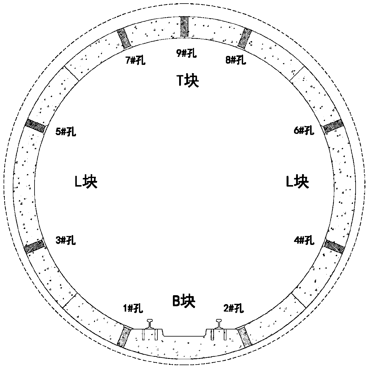
[0041] This embodiment is a water diversion tunnel engineering project. Such as figure 1 As shown, the project adopts a hexagonal segment with 4 rings, which is divided into top T block, bottom B block, and waist L block. It contains 9 grouting holes in total. The number and position of the grouting holes are as follows figure 1 shown. The TBM used in this project has 27 trolleys, which are numbered from front to back as No. 1 trolley, No. 2 trolley ... No. 27 trolley. The grouting machine in the middle and front part of this project is located on the No. 4 trolley, and the grouting machine at the tail is located on the No. 22 trolley. The specific construction method is as follows:

[0042] Step 1, reserve holes on the segment, and the holes are used for pea stone dredging and grouting;

[0043] Such as figure 1 As shown, there are 1# holes and 2# holes on both sides of the block B at the bottom; 3# holes and 5# holes are respectively set on the lower and upper parts of ...


PUM


Abstract

The invention relates to the technical field of tunnel construction, in particular to a construction method for wall-back backfilling of a double-shield TBM. The construction method comprises the following steps that 1, a pea gravel blow filling and grouting hole is reserved in a segment; 2, the segment is spliced; 3, the top of the segment is filled with pea gravels; 4, a bottom arch is subjectedto grouting; 5, the two sides of the segment are subjected to grouting through a grouting machine in the front middle portion of a tunneling machine; 6, the top of the segment is subjected to primarytop grouting through the grouting machine on the tail portion of the tunneling machine; and 7, after a tunnel is formed, the top of the segment is subjected to secondary top grouting. The two sides of the segment are subjected to grouting in advance through the grouting machine in the front middle portion of the tunneling machine, and the grouting positions of the two sides of the segment are more front, so that the procedure pressure of tail grouting is reduced, and the procedure cycle of TBM construction is further compact. Besides, the time interval between tunnel forming and two-side grouting is also shortened, and the damage of weak surrounding rock lower roof fall, shrinkage and other geological risks to the quality of the formed tunnel is reduced.

Description

technical field [0001] The invention relates to the technical field of tunnel construction, in particular to a construction method for backfilling behind the wall of a double-shield TBM. Background technique [0002] The double-shield TBM construction method belongs to the shield method, which is a shield construction method specially used in hard rock areas in underground engineering. This construction method can realize tunnel excavation and segment lining at the same time. [0003] The construction efficiency of double-shield TBM is much higher than that of shield tunneling, but the backfilling of the segment wall cannot be completed simultaneously with the grouting construction of the shield tunnel. The traditional backfilling of the TBM wall needs to be operated in four steps: 1. Simultaneous backfilling of pea pebbles; 2. Bottom arch mortar; 3. Tail cement slurry pouring; 4. Consolidation injection of 3 grouting holes on the vault after tunnel penetration. [0004] Ho...

Claims


Application Information

Patent Timeline
Patent Type & Authority Applications(China)
IPC IPC(8): E21D9/087E21D11/08E21D11/10
CPCE21D9/087E21D11/08E21D11/10
Inventor 柴华胡天然刘凤凡罗小荣陈卓陈强
Owner CHINA RAILWAY NO 2 ENG GRP CO LTD
Why Eureka
Try Eureka