Anti-freezing method and floor heating system

A technology for floor heating and water storage tanks, applied in hot water central heating systems, heating systems, heating methods, etc., can solve the problem of high energy consumption and achieve the effect of reducing production and application costs

Active Publication Date: 2020-08-28
NINGBO AUX ELECTRIC +1
View PDF28 Cites 4 Cited by
  • Summary
  • Abstract
  • Description
  • Claims
  • Application Information

AI Technical Summary

Problems solved by technology

[0003] The problem solved by the invention is that the ene

Method used


Image

  • Anti-freezing method and floor heating system
  • Anti-freezing method and floor heating system
  • Anti-freezing method and floor heating system

Examples


Embodiment Construction

[0048] In order to make the above objects, features and advantages of the present invention more comprehensible, specific embodiments of the present invention will be described in detail below in conjunction with the accompanying drawings.

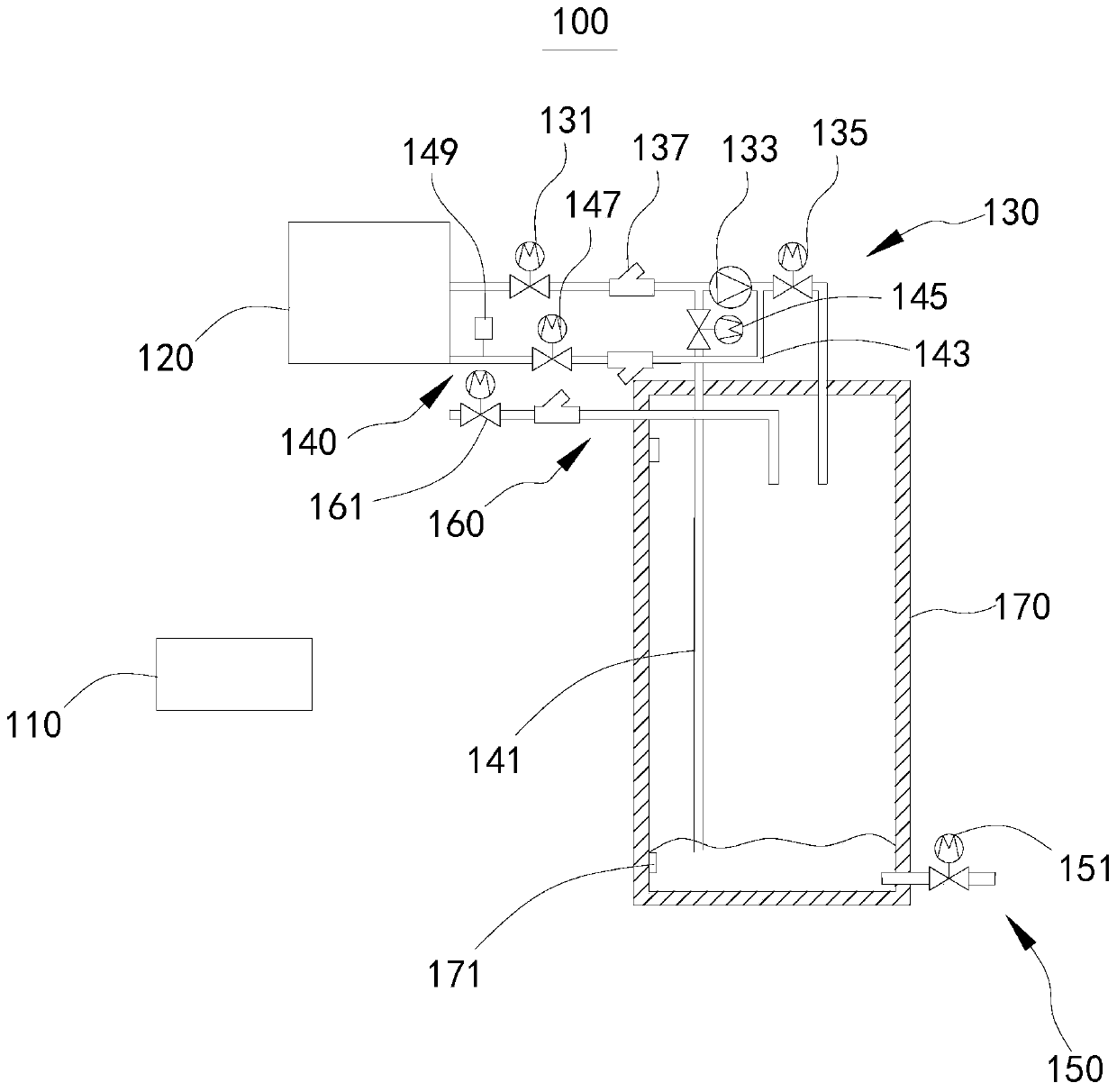
[0049] see figure 1 , figure 1 Shown is a schematic structural diagram of the floor heating system 100 provided by the embodiment of the present invention. The floor heating system 100 provided by the embodiment of the present invention has the characteristics of energy saving and high degree of automation.

[0050] In the embodiment of the present invention, the floor heating system 100 includes a controller 110 , a floor heating device 120 , a water storage pipeline 130 , a return water pipeline 140 , a drainage pipeline 150 , a water supply pipeline 160 and a water storage tank 170 . One end of the water storage pipeline 130 and the return water pipeline 140 are respectively connected to the water storage tank 170, and the other end is...


PUM


Abstract

The invention provides an anti-freezing method and a floor heating system. The anti-freezing method is applied to the floor heating system. The floor heating system comprises a floor heating device, awater storage pipeline, a water return pipeline and a water storage tank, wherein one end of the water storage pipeline and one end of the water return pipeline are connected with the water storage tank, and the other ends of the water storage pipeline and water return pipeline are connected with the floor heating device. The anti-freezing method comprises steps as follows: when a preset water storage anti-freezing condition is met, the floor heating device is controlled to shut down; the water storage pipeline is controlled to input water in the floor heating device into the water storage tank for storage; when a preset startup heating condition is met, the water return pipeline is controlled to input water stored in the water storage tank into the floor heating device; and the floor heating device is controlled to be stared. The anti-freezing method has the characteristics of saving resources, reducing energy consumption and being high in degree of automation.

Description

technical field [0001] The invention relates to the field of antifreeze technology, in particular to an antifreeze method and a floor heating system. Background technique [0002] At present, floor heating devices on the market generally use two methods to prevent freezing when the ambient temperature is lower than the set temperature and the user does not use it for a long time. First, the floor heating device is intermittently started to prevent freezing, and the heating devices such as water pumps and gas wall-hung boilers in the control system are intermittently started and stopped to circulate and heat the water in the system. This method causes a large amount of energy consumption such as electricity and gas; Second, the valve is manually opened to drain the water in the floor heating device directly. This method causes a great waste of water resources, and manual operation is relatively inconvenient. Contents of the invention [0003] The problem solved by the inve...

Claims


Application Information

Patent Timeline
IPC IPC(8): F24D3/02F24D3/10F24D19/10
CPCF24D3/02F24D3/1058F24D19/0092F24D19/0095F24D19/1015
Inventor 李傲冬
Owner NINGBO AUX ELECTRIC
Why Eureka
Try Eureka