Carbon dioxide fracturing device and series connection method

A carbon dioxide and cracker technology, which can be used in weapon accessories, blasting cylinders, offensive equipment, etc., and can solve problems such as easy wear and tear of wires

Pending Publication Date: 2020-08-28
HEBEI YUSN CHEM GROUP
2 Cites 2 Cited by

AI-Extracted Technical Summary

Problems solved by technology

[0003] The invention proposes a carbon dioxide cracker, which solves the problem that the wir...

Method used

Concrete, based on the various problems that the current series-connected cracking cylinders that are described based on the background technology occur, the problems such as wear and tear that the wire 3 is left on the outside can cause. According to the technical prejudice, the opening of holes will lead to carbon dioxide gas leakage. The reason is that, as a carbon dioxide cracker with blasting function, during the process of gasification and expansion of carbon dioxide in the cracking cylinder, a large pressure is generated on the bursting disc 1, which requires a The bursting disc 1 of the first through hole 2 cannot be broken in advance. Once it is broken in advance, the detonation will not be successful at least, and the workers will be injured at the worst. It is difficult to break the bursting disc when the pressure in the cracking cylinder reaches the requirement. This design not only realizes the realization, but also can work stably, which brings many benefits. In the bursting disc 1 is provided with a first through hole 2, which enables the positive and negative lead wires 3 to pass through the first through hole 2, and the positive and negative lead wires 3 are all set in the cracking cylinder, which can ensure the stability of the circuit and is not subject to blasting. environmental impact, and with this design, the bursting disc 1 is not used as a current path, and the outer wall of the cracking cylinder is also not charged, which avoids the need to leave a wire 3 outside the series of cracking cylinders in the prior art, so that multiple When the cracking cylinder is placed in the borehole of the rock wall, the wire 3 left on the outside may wear and tear, causing the detonation circuit to be destroyed.
In the present embodiment, also comprise excitation tube in cracking cylinder, the packaging film 16 of excitation tube is cylinder shape, and material is plastic composite film or plastic cross film, and cost is low, and waterproof moisture-proof anti-static, simple in structure, uses It is more convenient. The two ends of the cylindrical packaging film 16 are provided with buckles for sealing the cylindrical packaging film 16. The sealing performance is good, which can not only prevent the leakage of the medicament 17 used for excitation, but also prevent the entry of liquid carbon dioxide, which will affect the The trigger 8 in the packaging film 16 is ignited, and the cracking cylinders connected in series are connected together through the wire 3. The trigger 8 is connected to the wire 3 for ignition, and the matching material is a packaging film made of plastic composite film or plastic cross film. 16, the safety of the overall device is high, the plastic composite film can be completely burned when the agent 17 is burned, no plastic fragments will be generated, the safety is high, no recycling is required, and the environment will not be polluted, and compared with plastic pipes, The plastic packaging film 16 is more convenient to mark. At the same time, this excitation tube adopts an automatic production line similar to ham sausage to realize automatic drug filling, and the production efficiency is high. Compared with the traditional manual packaging of plastic tubes, it greatly reduces the workload and improves production efficiency. , the production cost is reduced, and the excitation tube using this structure is smaller than the excitation tube in the prior art, which can increase the storage space of carbon dioxide in the liquid storage tube 5 .
In the present embodiment, lead wire 3 is copper core enameled wire, and this kind lead wire 3 is made up of two parts of conductor and insulation layer, and after bare wire is softened by annealing, paints again through multiple times, bakes and forms, and is used in this st...

Abstract

The invention relates to the technical field of blasting devices, and discloses a carbon dioxide fracturing device and a series connection method. The carbon dioxide fracturing device comprises a fracturing barrel, wherein a blasting sheet is arranged in the fracturing barrel; a first through hole is formed in the blasting sheet; and the first through hole is used for enabling a conductive wire topenetrate through. The carbon dioxide fracturing device further comprises a sealing element which is used for being filled into a gap between the first through hole and the conductive wire. Through the technical scheme, the problem that a stable series loop cannot be formed during series connection for the carbon dioxide fracturing device in the prior art, is solved.

Application Domain

Blasting cartridges

Technology Topic

Composite materialEngineering +2

Image

  • Carbon dioxide fracturing device and series connection method
  • Carbon dioxide fracturing device and series connection method
  • Carbon dioxide fracturing device and series connection method

Examples

  • Experimental program(1)

Example Embodiment

[0047] The following will clearly and completely describe the technical solutions in the embodiments of the present invention in conjunction with the embodiments of the present invention. Obviously, the described embodiments are only a part of the embodiments of the present invention, rather than all the embodiments. Based on the embodiments of the present invention, all other embodiments obtained by those of ordinary skill in the art without creative work are related to the protection scope of the present invention.
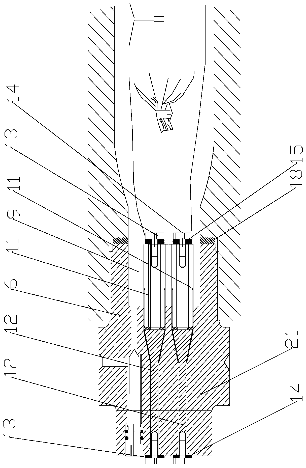
[0048] Such as Figure 1 ~ Figure 4 As shown, this embodiment proposes
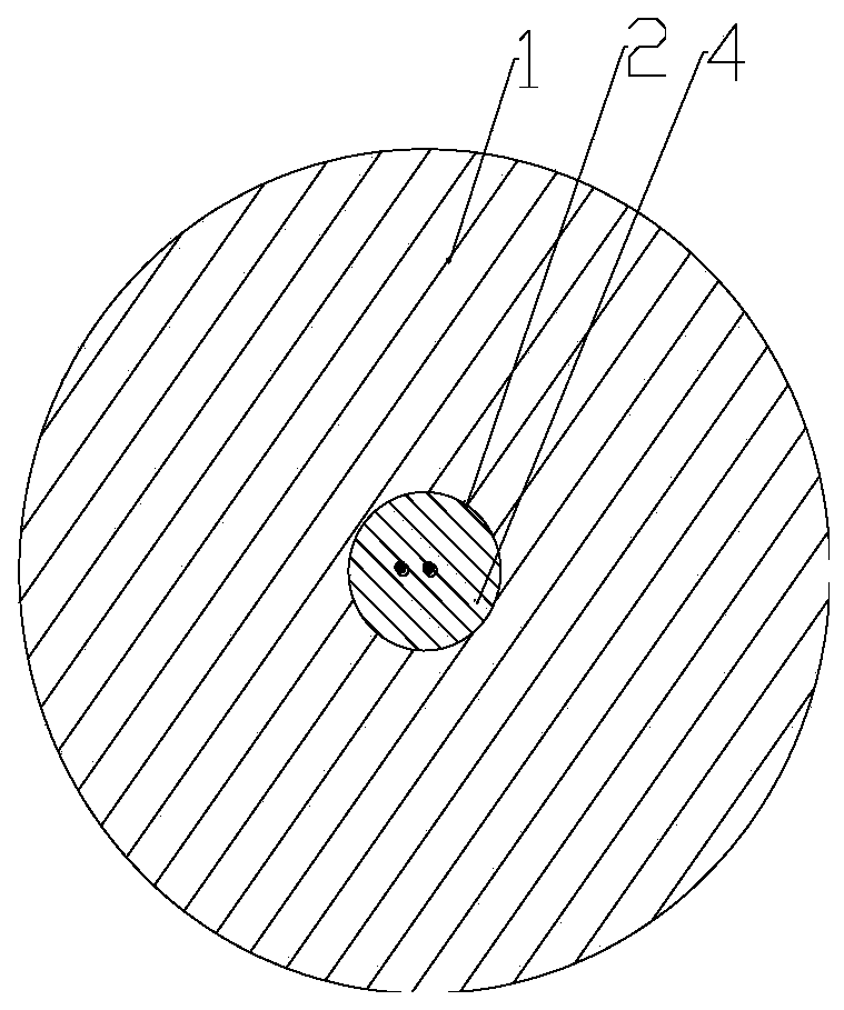
[0049] A carbon dioxide rupture device includes a rupture cylinder. The rupture cylinder is provided with a rupture disc 1. A first through hole 2 is provided on the rupture disc 1. The first through hole 2 is used to pass a wire 3 through. The carbon dioxide rupture device Also includes
[0050] The sealing member 4 is used to be arranged in the gap between the first through hole 2 and the wire 3.
[0051] In this embodiment, the rupture disc 1 is installed in the rupture tube of the carbon dioxide cracker. When the carbon dioxide in the rupture tube rapidly vaporizes and expands when it heats up, when the pressure exceeds the bursting disc 1 in the rupture tube, it will burst Piece 1 is broken, causing the gas to rush out of the fracturing cylinder, instantly generating a strong impact force to achieve the purpose of blasting. When multiple fracturing cylinders are connected in series, a wire 3 is required to connect the multiple fracturing cylinders together and use the same one The power switch can achieve the purpose of detonating multiple rupture devices. In this embodiment, a first through hole 2 is provided on the rupture disc 1 in the rupture cylinder, and the wire 3 passes through the first through hole 2, and The sealing member 4 seals the gap between the first through hole 2 and the wire 3, and the gap between the first through hole 2 and the wire 3 can be blocked by a structural adhesive, so as to realize the series connection of multiple fracturing cylinders.
[0052] Specifically, based on the various problems of the current series of fracturing cylinders described in the background art, the wires 3 left on the outside will cause wear and other problems. Prior to this, people in the field had certain technical biases on the opening of the rupture disc 1. , I feel that openings will cause carbon dioxide gas leakage. The reason is that as a carbon dioxide cracker with blasting function, during the process of gasification and expansion of carbon dioxide in the cracking cylinder, a great pressure is generated on the rupture disc 1, which requires the first pass Bursting disc 1 of hole 2 cannot be broken in advance. Once broken in advance, the detonation will be unsuccessful, and workers will be injured in severe cases. Therefore, if you want to open the first through hole 2 on the bursting disc 1, you must not only make the lead 3 pass smoothly, It is also necessary to ensure that the bursting disc is broken when the pressure in the rupture tube reaches the requirements. This is difficult to achieve. This design is not only realized, but also can work stably, which brings many benefits. Set on the bursting disc 1. The first through hole 2 enables the positive and negative leads 3 to pass through the first through hole 2, and the positive and negative leads 3 are arranged in the rupture cylinder, which can ensure the stability of the circuit and is not affected by the blasting environment Moreover, in this design, the rupture disc 1 is not used as a path for current, and the outer wall of the rupture cylinder is not charged, which avoids the need to leave a wire 3 outside the rupture cylinder in series in the prior art, so that multiple rupture cylinders When placed in a borehole in the rock wall, the wires 3 left on the outside may be worn out, causing the detonation circuit to be destroyed.
[0053] Further, the diameter of the first through hole 2 is less than or equal to 3 mm.
[0054] In this embodiment, through repeated experiments, a first through hole is punched in the center of the rupture disc. The diameter can be designed to be less than or equal to 3mm. This design can realize that the rupture disc 1 with the first through hole 2 is not broken in advance. Or the negative lead 3 passes through the first through hole 2. If the diameter of the first through hole 2 is larger than this range, it is very likely that the carbon dioxide gas in the fracturing cylinder will increase due to the pressure gradually increasing during the expansion process. Leakage from the gap between the first through hole 2 and the wire 3, and will further cause the rupture disc 1 to rupture prematurely. When the thickness of the rupture disc 1 is 12mm, the diameter of the first through hole 2 can be 3mm. When the thickness is 3mm, the diameter of the first through hole 2 can be 2mm. Except for this solution, when the thickness of the rupture disc 1 is too small, such as a 4mm thick rupture disc 1, then a 3mm first through hole 2 will be Make the rupture disc 1 rupture in advance. At this time, you can also punch two first through holes 2 symmetrically at the center of the rupture disc 1, with a diameter less than or equal to 1.5mm, and the two first through holes 2 are respectively pierced with a positive lead 3 and the negative lead 3 can avoid the problem of premature breakage caused by a 3mm aperture.
[0055] Further, the wire 3 is an enameled wire.
[0056] In this embodiment, the wire 3 is a copper core enameled wire. This wire 3 is composed of a conductor and an insulating layer. After the bare wire is softened by annealing, it is painted and baked many times. Advantages of using this structure The reason is that there is no gap between the outer skin of the enameled wire and the bare wire. The insulating layer is attached to the bare wire in the form of paint. The outer skin of the common wire 3 is wrapped outside the bare wire, leaving between the bare wire and the outer skin. The gap, because the wire 3 needs to pass through the first through hole 2 on the rupture disc 1, once there is a gap between the outer skin and the bare wire, the carbon dioxide in the fracturing cylinder is likely to leak through this gap during the expansion process, and lose its performance. Functionality, so the form of enameled wire is used to avoid problems.
[0057] Further, the rupture tube includes
[0058] The liquid storage tube 5 is provided with a port 1 9 and a port 2 10,
[0059] The filling head 6 is set at the mouth 9 of the liquid storage tube 5, and the two ends of the filling head 6 are connected with the wires 3,
[0060] The energy venting head 7 is set at the mouth two 10 of the liquid storage tube 5, and the burst disc 1 is set between the energy venting head 7 and the liquid storage tube 5,
[0061] The exciter 8 is arranged in the liquid storage tube 5, the wire 3 passes through the liquid storage tube 5 and the energy discharge head 7, and the wire 3 is connected to the exciter 8.
[0062] In this embodiment, the fracturing cylinder includes a filling head 6 and an energy venting head 7 connected to both ends of the liquid storage tube 5. The filling head 6 is threadedly connected to the port 9 of the liquid storage tube 5, and the energy venting head 7 also passes through The thread is connected to the second port 10 of the liquid storage tube 5. The wire 3 is connected to the exciter 8 in the liquid storage tube 5. The wire 3 connected to the exciter 8 passes through the first through hole 2 on the rupture disc 1 and discharges energy Head 7, filling head 6 is used to press liquid carbon dioxide through port 9 into the liquid storage tube 5 through a hydraulic device, and the liquid storage tube 5 is used to hold carbon dioxide. When the wire 3 transmits current to the exciter 8, it is excited The device 8 can make the carbon dioxide in the liquid storage tube 5 expand. When the pressure in the liquid storage tube 5 is greater than the pressure of the bursting disc 1 with the first through hole 2, the bursting disc 1 ruptures, and the carbon dioxide gas with impact force is removed from The liquid storage tube 5 passes through the bursting disc 1 to the energy venting head 7. The energy venting head 7 is equipped with a venting hole. The gas is released from the venting hole to achieve blasting. The bursting disk 1 with different pressure specifications can be used to achieve For accurate control of the blasting force, the diameter of the first through hole 2 is preferably designed to be less than or equal to 3mm, which can ensure that the bursting disc 1 blasts under the set pressure.
[0063] Further, the filling head 6 includes
[0064] Insulating tube 11, two or more,
[0065] The center electrode 12 is arranged in the insulating tube 11 and connected to the lead 3,
[0066] The positive terminal 13 is arranged at both ends of the center electrode 12, and the wire 3 connects the exciter 8 and the positive terminal 13,
[0067] The negative terminal 14 is arranged at both ends of the center electrode 12 and is arranged beside the positive terminal 13. The wire 3 connects the exciter 8 and the negative terminal 14.
[0068] In this embodiment, the filling head 6 includes an insulating tube 11, and there are two insulating tubes 11, and there are also two center electrodes 12 therein. Both ends of the two center electrodes 12 are provided with a positive terminal 13 and a negative terminal 14 respectively. Due to the need to realize the series connection of multiple fracturing cylinders, the central electrode 12 in the insulating tube 11 is used to conduct electricity, and the insulating tube 11 covered by the insulating tube 11 prevents current from passing through the outer wall of the filling head 6 so that the outer wall is charged. It is realized that the current of the positive and negative poles pass through the filling head 6 to form a loop, and the positive and negative wires 3 are arranged in the cracking cylinder, which avoids the hidden danger of the wire 3 being worn out by the wire 3 outside.
[0069] Further, the filling head 6 also includes
[0070] The insulating pad 15 is arranged between the positive terminal 13 and the insulating tube 11 and between the negative terminal 14 and the insulating tube 11.
[0071] The two center electrodes 12 are arranged in the two insulating tubes 11, and a tapered sealing surface is used between the mother body of the filling head 6. Under the action of the hollow core compression screw, the tapered surface and the insulating pad 15 are compressed to achieve Sealing effect, and the insulating pad 15 is insulated from the center electrode 12 and the hollow-core compression screw
[0072] Further, the rupture tube also includes
[0073] The excitation tube is set in the liquid storage tube 5, the excitation tube includes
[0074] The packaging film 16 is a plastic composite film or a plastic cross film, and the exciter 8 is arranged in the packaging film 16,
[0075] The medicine 17 is arranged in the packaging film 16.
[0076] In this embodiment, an excitation tube is also included in the fracturing cylinder. The packaging film 16 of the excitation tube is cylindrical, made of plastic composite film or plastic cross-film, low cost, waterproof, moisture-proof and static-proof, simple structure, and more convenient to use. Both ends of the cylindrical packaging film 16 are provided with buckles for sealing the cylindrical packaging film 16, which has good sealing performance, which can not only prevent the leakage of the medicament 17 used for excitation, but also prevent liquid carbon dioxide from entering and affecting the packaging film 16. The inner exciter 8 is ignited, and the fracturing cylinders connected in series are connected together by the wire 3. This exciter 8 is connected to the wire 3 for ignition, and is matched with the packaging film 16 made of plastic composite film or plastic cross film, so that The overall device has high safety. The plastic composite film can be completely burned when the medicament 17 is burned. There will be no plastic fragments. The safety is high. It does not need to be recycled and does not pollute the environment. Compared with plastic tubes, plastic packaging films 16 The marking is more convenient. At the same time, this excitation tube uses an automated production line similar to ham sausage to achieve automated loading. The production efficiency is high. Compared with the traditional plastic tube manual packaging, it greatly reduces the workload, improves the production efficiency, and reduces The production cost, and the use of the excitation tube with this structure is smaller than the excitation tube in the prior art, so that the carbon dioxide storage space in the liquid storage tube 5 can be increased.
[0077] Further, the rupture tube also includes
[0078] The second sealing gasket 18 is arranged between the rupture disc 1 and the liquid storage tube 5 or between the filling head 6 and the liquid storage tube 5.
[0079] In this embodiment, the filling head 6 is screwed to the port 9 of the liquid storage tube 5, and the energy venting head 7 is also screwed to the port 2 10 of the liquid storage tube 5. Because the filling head 6 is connected to the liquid storage tube 5 , The bleeder head 7 and the liquid storage tube 5 are all rigidly connected, and the liquid storage tube 5 is used to hold carbon dioxide. When the wire 3 transmits current to the exciter 8 in the liquid storage tube 5, the exciter 8 can make The gas in the liquid storage tube 5 expands. If the ports 9 and 10 of the liquid storage tube 5 are not tightly sealed, the gasified carbon dioxide will leak in advance, and the gas will not pass through the venting head 7 by breaking the rupture disc 1 Therefore, a second sealing gasket 18 is provided between the discharge head 7 and the liquid storage tube 5, or between the filling head 6 and the liquid storage tube 5, which can play a good sealing role and prevent the leakage of carbon dioxide gas. ,
[0080] Furthermore, the second sealing gasket 18 is further provided with a second through hole 19, and the diameter of the second through hole 19 is not less than the diameter of the port two 10 and the port one 9 of the liquid storage tube 5.
[0081] In this embodiment, a second through hole 19 is also provided on the second sealing pad 18, and the wire 3 can be passed through the second through hole 19, so that the wire 3 can pass from the positive terminal 13 of the filling head 6 or The negative terminal 14 is led out and passes through the second through hole 19, and is connected to the exciter 8 in the liquid storage tube 5. The diameter of the second through hole 19 is larger than that of the port two 10 and the port one 9 of the liquid storage tube 5. Diameter, so it will not affect the storage of carbon dioxide in the liquid storage tube 5, avoid the installation of the second gasket 18, reduce the storage space of carbon dioxide, and better realize the filling head 6 and the liquid storage tube 5, or leakage Capable of sealing between the head 7 and the liquid storage tube 5.
[0082] Further, it also includes
[0083] The sleeve 20 is arranged outside the fracturing cylinder, and is used for piercing the wire 3 inside to connect two adjacent fracturing cylinders.
[0084] In this embodiment, when a plurality of fracturing cylinders are connected in series, it is necessary to connect the plurality of fracturing cylinders in series with a wire 3, and the wire 3 passes through the fracturing cylinder, but the wire 3 between the two fracturing cylinders When exposed to the outside, when used, the crazing cylinder is very likely to be worn away from the rock wall at the installation location. Since the wire 3 of this structure is in the form of enameled wire, once it is worn out, it is likely to be dangerous. In order to avoid this situation, A sleeve 20 is arranged between the two fracturing cylinders, and the wire 3 is inserted into the sleeve 20 to effectively prevent the conductor 3 from being exposed. The sleeve 20 is connected to two adjacent fracturing cylinders. The connection method can be in The sleeve 20 is provided with internal threads at the front and rear. The front end of the filling head 6 of the fracturing cylinder is provided with external threads, and the rear end of the energy venting head 7 is provided with external threads, so that the sleeve 20 can connect the filling of a fracturing cylinder through a threaded connection. The mounting head 6 is connected with the energy venting head 7 of the adjacent fracturing cylinder, and the purpose of detonating multiple fracturing devices can be achieved by using the same power switch.
[0085] A series method, characterized in that it comprises
[0086] Open the first through hole 2 on the rupture disc 1,
[0087] Lead out two wires 3 from the power supply, and both pass through the first through hole 2 on the bursting disc 1 of the rupture cylinder.
[0088] The seal 4 is set in the gap between the wire 3 and the first through hole 2,
[0089] Install the sleeve 20 between two adjacent fracturing cylinders,
[0090] The two wires 3 coming out of the last cracking cylinder pass through the sleeve 20 and are connected to the other cracking cylinder,
[0091] A plurality of rupture cylinders are connected to form a series loop through the wire 3.
[0092] The above are only the preferred embodiments of the present invention and are not intended to limit the present invention. Any modification, equivalent replacement, improvement, etc. made within the spirit and principle of the present invention shall be included in the protection scope of the present invention within.

PUM

PropertyMeasurementUnit
Diameter<= 3.0mm

Description & Claims & Application Information

We can also present the details of the Description, Claims and Application information to help users get a comprehensive understanding of the technical details of the patent, such as background art, summary of invention, brief description of drawings, description of embodiments, and other original content. On the other hand, users can also determine the specific scope of protection of the technology through the list of claims; as well as understand the changes in the life cycle of the technology with the presentation of the patent timeline. Login to view more.
Why Eureka
Try Eureka