Laser tracker precision on-site evaluation system based on multi-station method

A laser tracker and evaluation system technology, which is applied in the direction of instruments, optical devices, and measuring devices, can solve the problems of high cost, unsuitable on-site evaluation of laser tracker accuracy, and high precision requirements of three-coordinate measuring machines. Effect of Overall Measurement Accuracy

Active Publication Date: 2020-08-28
INST OF MACHINERY MFG TECH CHINA ACAD OF ENG PHYSICS
View PDF7 Cites 5 Cited by
  • Summary
  • Abstract
  • Description
  • Claims
  • Application Information

AI Technical Summary

Problems solved by technology

Or use a three-coordinate measuring machine to track the calibration method of the measurement system, which requires additional testing equipment, and has high requirements for the accuracy of the three-coordinate measuring machine, which is not suitable for on-site measurement
In addition, most of the detection methods for intelligent manufacturing equipment using laser trackers require self-calibration, resulting in low measurement accuracy of spatial position coordinates, and accurate on-site evaluation o

Method used


Image

  • Laser tracker precision on-site evaluation system based on multi-station method
  • Laser tracker precision on-site evaluation system based on multi-station method
  • Laser tracker precision on-site evaluation system based on multi-station method

Examples


Embodiment Construction

[0063] In order to make the purpose, technical solutions and advantages of the present invention clearer, the present invention will be further described in detail below in conjunction with the examples and accompanying drawings. As a limitation of the present invention.

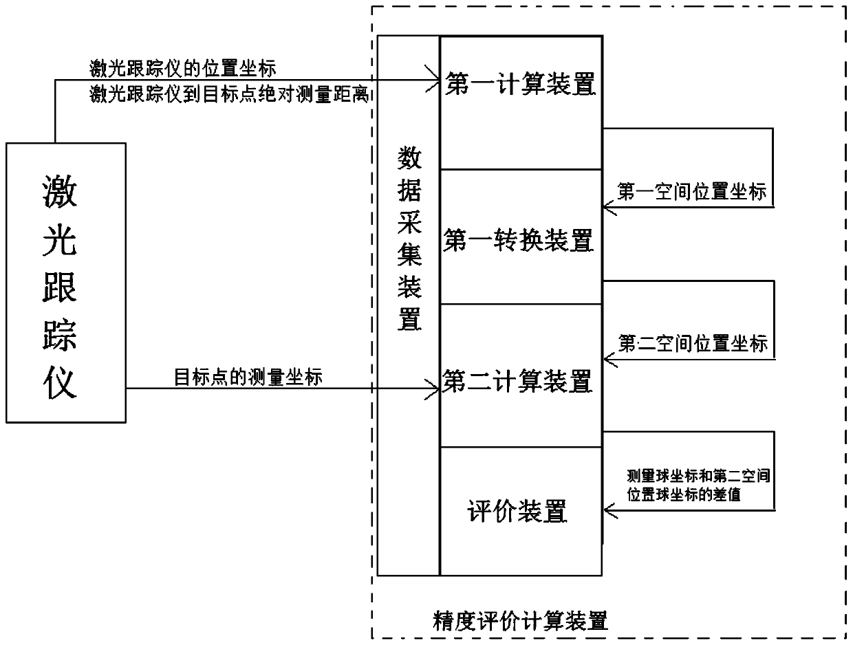
[0064] Such as figure 1 As shown, a laser tracker accuracy on-site evaluation system based on the multi-station method of the present invention mainly includes two parts, the laser tracker accuracy on-site measurement program and the laser tracker accuracy on-site data processing and evaluation program.

[0065] 1. On-site measurement scheme of laser tracker precision

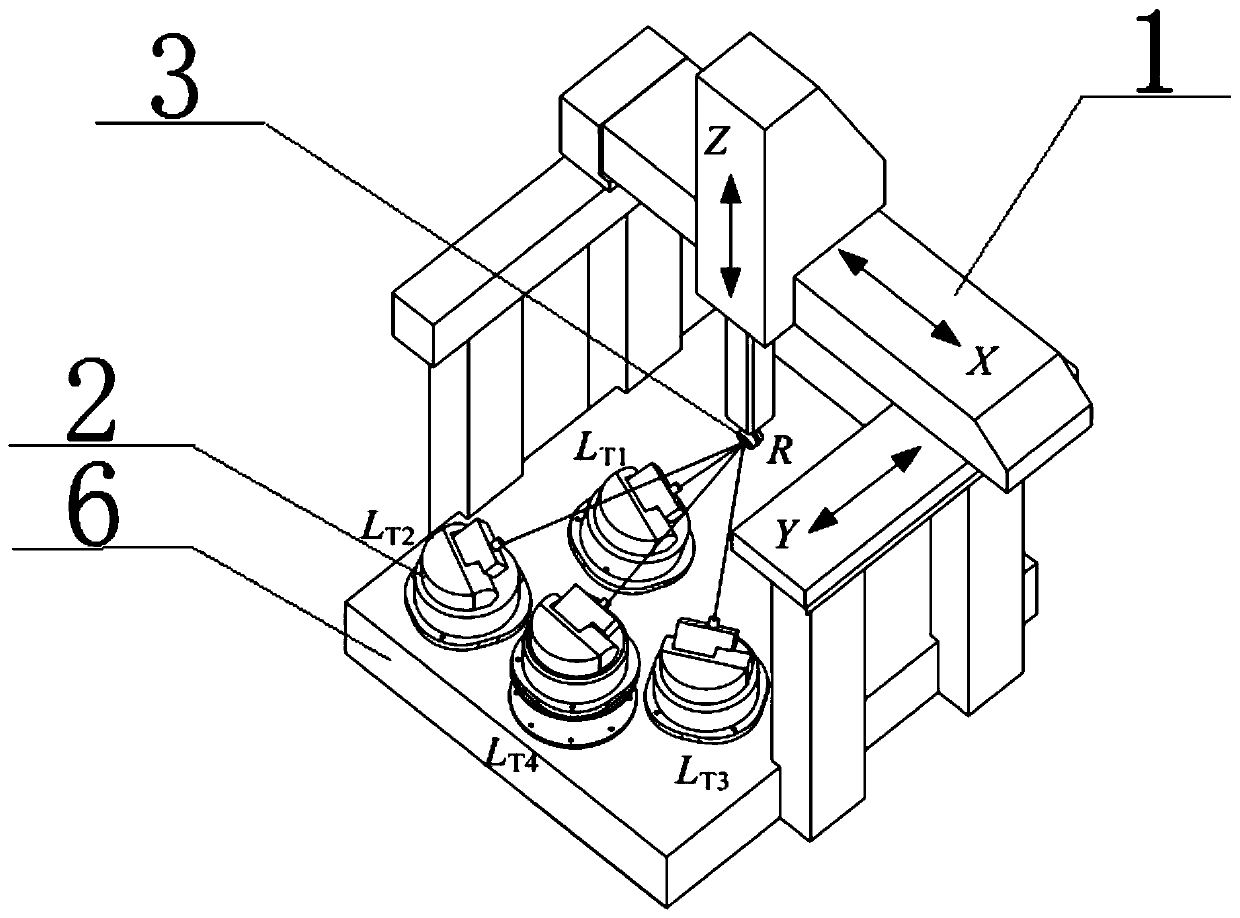
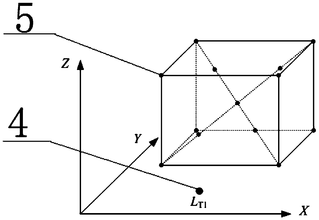
[0066] When measuring, such as figure 1 As shown, the laser tracker is placed in four positions LTi (i=1, 2, 3, 4) that are not coplanar on the workbench for measurement, and the measurement track at each position is the same (one laser tracker can also be used The instrument is placed in at least 4 different positions for measurement resp...


PUM


Abstract

The invention discloses a laser tracker precision on-site evaluation system based on a multi-station method. The laser tracker precision on-site evaluation system comprises measuring point motion driving equipment, a plurality of laser trackers and a precision evaluation calculating device, wherein the laser trackers track and measure measurement coordinates of each target point on the measuring point motion driving equipment under a laser tracker coordinate system B and absolute measurement distances from the laser trackers to the target points; the precision evaluation calculating device calculates first spatial position coordinates of the target points under a coordinate system A of the measuring point motion driving equipment according to the absolute measurement distances from the laser trackers to the target points; coordinate transformation is carried out to obtain second spatial position coordinates under the coordinate system B; and a difference value between a measurement coordinates of the target points and the second spatial position coordinates are calculated, and laser tracker measurement angle and measurement length precision evaluation can be obtained by adopting aprobabilistic method. The laser tracker precision on-site evaluation system has the advantages of being high in measurement speed, low in cost and the like in laser tracker precision on-site evaluation, and has higher on-site practicability and operability in measurement equipment with a theoretical coordinate position or a three-coordinate space precision detection process.

Description

technical field [0001] The invention relates to the field of precision detection and calibration of a laser tracker, in particular to an on-site evaluation system for the precision of a laser tracker based on a multi-station method. Background technique [0002] The laser tracker is an important large-scale space measurement datum, and has a wide range of applications in the geometric measurement of large-scale parts, assembly, and intelligent manufacturing equipment. The error of the laser tracker has a great influence on the measurement results, especially in the process of equipment / three-coordinate space accuracy detection. Therefore, it is necessary to evaluate the accuracy of the laser tracker to provide a reference for its high-precision measurement. [0003] In the detection process of intelligent manufacturing equipment, the accuracy of the laser tracker has a great influence on its spatial accuracy detection, especially the angular accuracy of the laser tracker. ...

Claims


Application Information

Patent Timeline
IPC IPC(8): G01B11/00
CPCG01B11/002G01B21/042
Inventor 韩林米良刘兴宝滕强唐强夏仰球陈衡杜坤周怡帆
Owner INST OF MACHINERY MFG TECH CHINA ACAD OF ENG PHYSICS
Why Eureka
Try Eureka