Preheating ring for epitaxial growth equipment, and epitaxial growth equipment

An epitaxial growth, preheating ring technology, applied in gaseous chemical plating, coating, electrical components and other directions, can solve the problems of reduced film uniformity, poor deposition efficiency, etc., to improve film uniformity, improve deposition efficiency, The effect of preventing turbulence and additional flow resistance

Pending Publication Date: 2020-08-28
BEIJING NAURA MICROELECTRONICS EQUIP CO LTD
View PDF6 Cites 1 Cited by
  • Summary
  • Abstract
  • Description
  • Claims
  • Application Information

AI Technical Summary

Problems solved by technology

Although rotating the substrate 130 during deposition can produce rotationally symmetric deposition, the film uniformity is reduced due to poor deposition efficiency due to dilution, especially near the edge of the substrate 130

Method used


Image

  • Preheating ring for epitaxial growth equipment, and epitaxial growth equipment
  • Preheating ring for epitaxial growth equipment, and epitaxial growth equipment
  • Preheating ring for epitaxial growth equipment, and epitaxial growth equipment

Examples


Embodiment 1

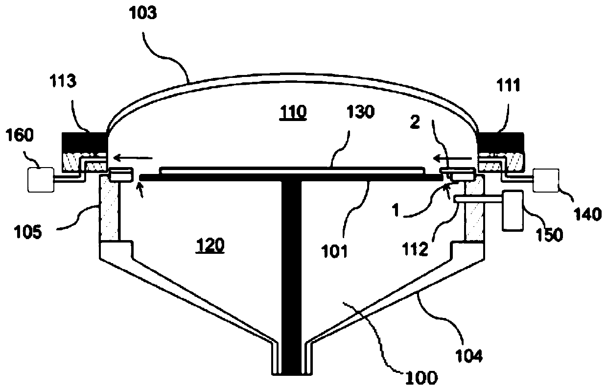
[0057] image 3 shows a schematic structural view of an epitaxial growth device according to an embodiment of the present invention, Figure 4 shows a schematic structural diagram of a preheating ring according to an embodiment of the present invention, Figure 5 shows a schematic structural view of an upper ring part according to an embodiment of the present invention, Figure 6 A schematic structural diagram of a lower ring part according to an embodiment of the present invention is shown.

[0058] Such as image 3 As shown, an epitaxial growth device of this embodiment includes: a reaction chamber, a base located in the reaction chamber, and a preheating ring, the preheating ring surrounds the outer periphery of the base, and there is a gap between the base and the base , One side of the reaction chamber is provided with a gas discharge area, and the other side is provided with a processing gas intake area, and the exhaust channel is close to the gas discharge area, and ...

Embodiment 2

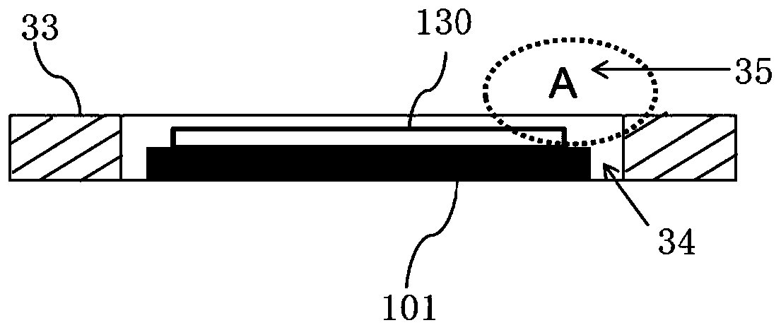
[0069] Figure 7 shows a schematic structural diagram of another preheating ring according to an embodiment of the present invention, Figure 8 show Figure 7 Partial enlarged view at B, Figure 9 It shows a schematic structural diagram of another upper ring part according to an embodiment of the present invention, Figure 10A schematic structural diagram of another lower ring part according to an embodiment of the present invention is shown.

[0070] Such as Figure 7-Figure 10 As shown, another preheating ring of the embodiment includes an upper ring part 2 and a lower ring part 1. The upper ring part 2 and the lower ring part 1 are stacked coaxially from top to bottom. The outer diameters of the ring parts 1 are equal, the inner diameter of the upper ring part 2 is smaller than the inner diameter of the lower ring part 1, and an exhaust passage is provided on one side of the upper ring part 2. The exhaust passage includes a plurality of through holes 25, which are dist...


PUM

PropertyMeasurementUnit
widthaaaaaaaaaa
widthaaaaaaaaaa
widthaaaaaaaaaa

Abstract

The invention discloses a preheating ring for epitaxial growth equipment, and the epitaxial growth equipment. The preheating ring comprises an upper ring part and a lower ring part, wherein the upperring part and the lower ring part are coaxially superposed from top to bottom, the outer diameter of the upper ring part is equal to that of the lower ring part, the inner diameter of the upper ring part is smaller than that of the lower ring part, an exhaust channel is arranged on one side of the upper ring part so as to rapidly discharge purified gas and treated gas, and the inner diameter of the upper ring part is smaller than that of the lower ring part, so that the upper ring part shields the inner circumferential surface of the lower ring part, the purified gas is prevented from flowingupwards through a gap between a substrate supporting piece and the lower ring part, turbulent flow and extra flow resistance are prevented from being formed near the edge of a substrate, the deposition efficiency of the edge of the substrate is improved, and the film forming uniformity of the substrate is improved.

Description

technical field [0001] The invention belongs to the field of semiconductor manufacturing equipment, and more specifically relates to a preheating ring for epitaxial growth equipment and epitaxial growth equipment. Background technique [0002] The continued reduction in the size of semiconductor devices relies on more precise control of the flow and temperature of process gases delivered to semiconductor processing chambers. Typically, in a semiconductor cross-flow processing chamber, processing gases may be delivered to the reaction chamber and directed past the surface of the substrate to be processed, the temperature of which may be controlled by a preheating ring surrounding the substrate support. control. [0003] figure 1 A schematic diagram of a prior art preheating ring is shown, as figure 1 As shown, the preheating ring is a ring structure with a flat upper surface. [0004] figure 2 It shows a schematic diagram of the flow of the preheating ring in the reacti...

Claims


Application Information

Patent Timeline
Patent Type & Authority Applications(China)
IPC IPC(8): H01L21/67C23C16/54C23C16/455
CPCH01L21/67207H01L21/67017C23C16/54C23C16/45502
Inventor 邓晓军
Owner BEIJING NAURA MICROELECTRONICS EQUIP CO LTD
Why Eureka
Try Eureka