
LED light-emitting unit and display panel

A technology of light-emitting unit and pixel unit, which is applied in the direction of electrical components, electric solid-state devices, circuits, etc., can solve the problems of low welding efficiency, weak welding, and small volume of light-emitting units, so as to improve welding efficiency, facilitate welding operations, reduce The effect of production costs

Inactive Publication Date: 2020-08-28
FOSHAN NATIONSTAR OPTOELECTRONICS CO LTD
View PDF8 Cites 0 Cited by
  • Summary
  • Abstract
  • Description
  • Claims
  • Application Information

AI Technical Summary

Problems solved by technology

[0004] With the rapid development of LED packaging technology, the process has gradually matured, and the requirements for dot pitches have become smaller and smaller. The market demand for dot pitches below P1.0mm has gradually increased, and the size of the corresponding light-emitting units has also continued to shrink. This kind of independent light-emitting unit is small in size, and it is difficult to weld, and it is not easy to be dropped due to weak welding, which is not conducive to transportation; due to the small size of a single light-emitting unit, more light-emitting units need to be welded to prepare a panel of the same size. The welding efficiency is low; in addition, because the panel of the same size needs to weld more light-emitting units, the wiring of the PCB board is more complicated, and the preparation cost of the PCB board is increased.

Method used


Image

  • LED light-emitting unit and display panel
  • LED light-emitting unit and display panel
  • LED light-emitting unit and display panel

Examples


Embodiment Construction

[0048]In order to make the technical problems solved by the present invention, the technical solutions adopted and the technical effects achieved clearer, the technical solutions of the embodiments of the present invention will be further described in detail below in conjunction with the accompanying drawings. Obviously, the described embodiments are only the technical solutions of the present invention. Some, but not all, embodiments. Based on the embodiments of the present invention, all other embodiments obtained by those skilled in the art without creative efforts fall within the protection scope of the present invention.

[0049] In the description of the present invention, unless otherwise clearly specified and limited, the terms "connected", "connected" and "fixed" should be understood in a broad sense, for example, it can be a fixed connection, a detachable connection, or an integrated ; It can be a mechanical connection or an electrical connection; it can be a direct ...


PUM


Abstract

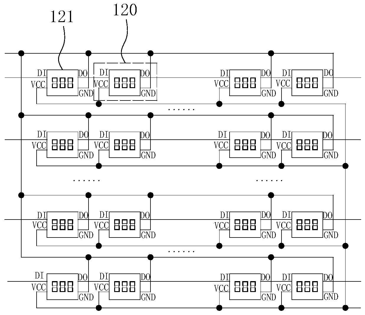
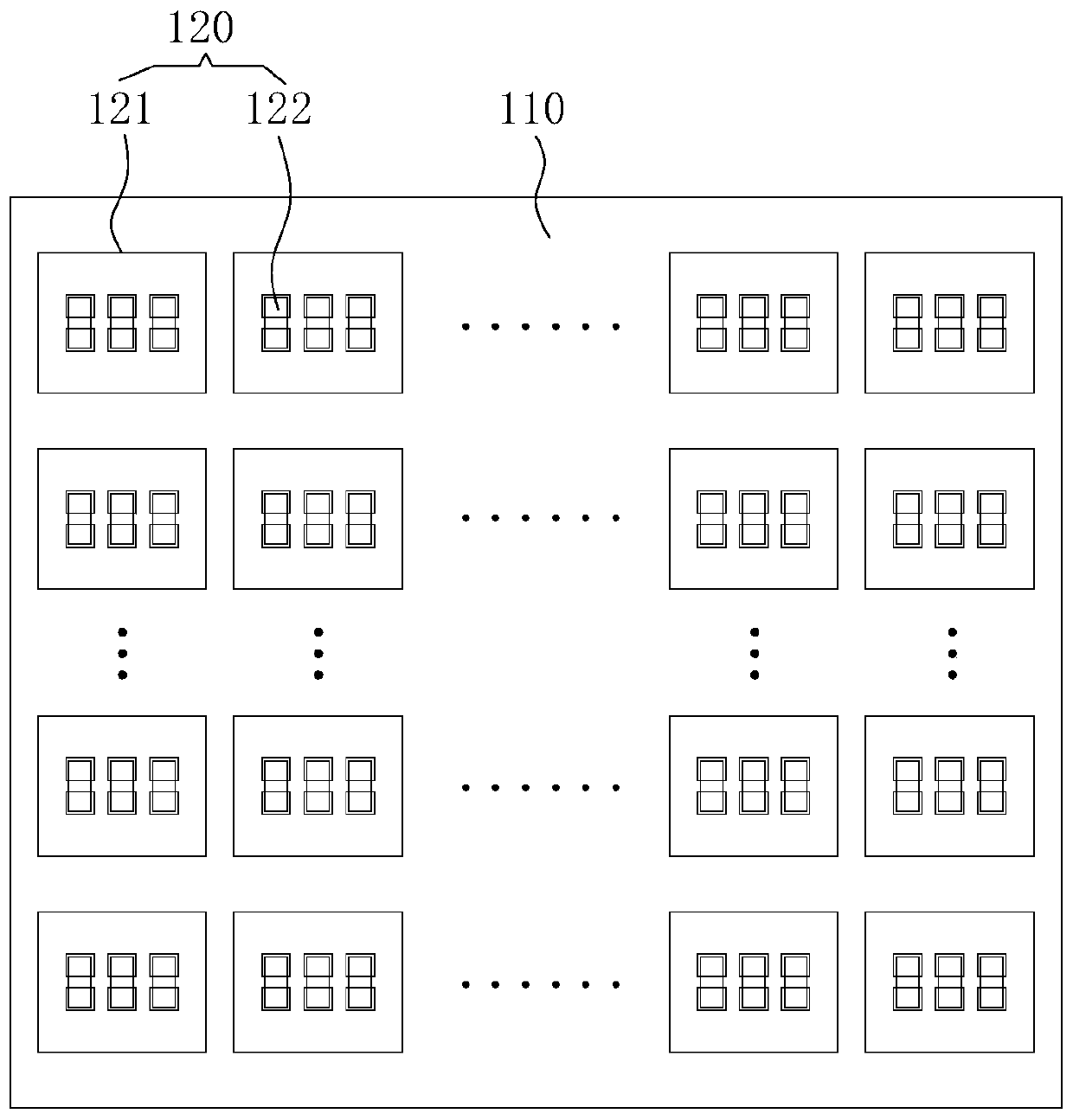
The invention discloses an LED light-emitting unit and a display panel. The LED light-emitting unit comprises a circuit board and a pixel unit array formed by n rows and m columns of pixel units on the circuit board, wherein both n and m are positive integers greater than or equal to 2. Each pixel unit comprises an IC chip and at least two LED light-emitting wafers, wherein the IC chip is used fordriving the LED light-emitting wafers to emit light. The IC chip comprises at least one data input pin, at least one data output pin, a power input pin and a grounding pin. The power input pins of the IC chips are electrically connected with each other, and the grounding pins of the IC chips are electrically connected with each other. In the same row of pixel units, the data input pin of one IC chip in two adjacent IC chips is electrically connected with the data output pin of the other IC chip. According to the invention, the welding efficiency and the welding firmness of welding the LED light-emitting unit to a large PCB are improved, the wiring of the large PCB is simplified on the premise of ensuring the number of pins of the display unit group, and the production cost is reduced.

Description

technical field [0001] The invention relates to the field of display technology, in particular to an LED light emitting unit and a display panel. Background technique [0002] Due to the advantages of high grayscale, large viewing angle, low power consumption and customizable screen shape, LED display screens are widely used in various fields such as industry, transportation, commercial advertising, and information release. [0003] The existing LED display screen is composed of a plurality of independent LED light-emitting units arranged in an array, and each light-emitting unit includes a plurality of LED light-emitting chips, a driver IC for driving a plurality of LED light-emitting chips, and a driver IC for carrying the LED light-emitting chips and The circuit board of the driver IC. The driver IC usually includes a data input pin, a data output pin, a power input pin and a ground pin. Multiple pins of the driver IC are respectively connected to pins on the opposite sid...

Claims


Application Information

Patent Timeline
IPC IPC(8): H01L33/48H01L33/62H01L25/16H01L27/15
CPCH01L25/167H01L27/156H01L33/48H01L33/62
Inventor 王昌奇秦快谢宗贤欧阳小波郭恒张普翔冯飞成
Owner FOSHAN NATIONSTAR OPTOELECTRONICS CO LTD
Learn More