Supercharge Your Innovation With Domain-Expert AI Agents!

Optical module debugging method, device, electronic equipment and storage medium

A technology of optical module and bias current, applied in the field of optical communication, can solve problems such as low efficiency

Active Publication Date: 2021-12-14
CHENGDU SUPERXON COMM TECH CO LTD
View PDF3 Cites 0 Cited by
  • Summary
  • Abstract
  • Description
  • Claims
  • Application Information

AI Technical Summary

Problems solved by technology

[0005] In view of this, the purpose of this application is to provide a method, device, electronic equipment and storage medium for optical module debugging, so as to improve the problem that the existing test method needs to cycle many times to find the final suitable value, making the problem of low efficiency

Method used


Image

  • Optical module debugging method, device, electronic equipment and storage medium
  • Optical module debugging method, device, electronic equipment and storage medium
  • Optical module debugging method, device, electronic equipment and storage medium

Examples


Embodiment approach

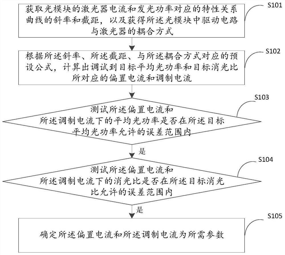
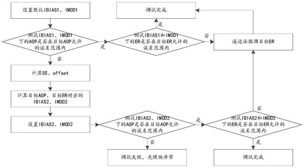
[0064] In order to quickly obtain the required bias current and modulation current, as an implementation, before the optical module is debugged, that is, before step S101, a fixed default bias current initial value IBIAS1 (preset Bias current) and modulation current initial value IMOD1 (preset modulation current), when debugging, directly test whether the average optical power under the bias current initial value IBIAS1 and modulation current initial value IMOD1 is within the allowable error range of the target average optical power If it is within the allowable error range of the target average optical power, then test whether the extinction ratio under the bias current initial value IBIAS1 and the modulation current initial value IMOD1 is within the allowable error range of the target extinction ratio; If the ratio is within the allowable error range, then the initial value of the bias current IBIAS1 and the initial value of the modulation current IMOD1 are the required param...


PUM


Abstract

The application relates to an optical module debugging method, device, electronic equipment and storage medium, and belongs to the technical field of optical communication. Obtain the slope and intercept of the characteristic relationship curve corresponding to the laser current and luminous power of the optical module, and obtain the coupling mode between the drive circuit and the laser in the optical module; according to the slope, intercept, and the preset formula corresponding to the coupling mode, calculate Adjust the bias current and modulation current corresponding to the target average optical power and target extinction ratio; test whether the average optical power under the bias current and modulation current is within the allowable error range of the target average optical power; if yes, test Whether the extinction ratio under the bias current and the modulation current is within the allowable error range of the target extinction ratio; if yes, determine the bias current and the modulation current as required parameters. This method only needs a few steps to obtain the final debugging parameters with high probability, avoids repeated cycle debugging, and greatly improves the debugging efficiency.

Description

technical field [0001] The application belongs to the technical field of optical communication, and in particular relates to an optical module debugging method, device, electronic equipment and storage medium. Background technique [0002] Average optical power (Average optical power, AOP) and extinction ratio (Extinction Ratio, ER) are the two most critical indicators of optical modules. Due to the different luminous efficiencies of lasers, these two indicators need to be individually debugged during the production of each optical module. The debugging methods of these two indicators have a great impact on the production efficiency of optical modules. Therefore, advanced and efficient debugging methods can greatly improve the production efficiency and capacity of optical modules. [0003] For directly modulated laser optical modules, AOP and ER are affected by the bias current (IBIAS) and modulation current (IMOD) provided by the laser drive circuit. The debugging process...

Claims


Application Information

Patent Timeline
Patent Type & Authority Patents(China)
IPC IPC(8): H01S5/00
CPCH01S5/0014
Inventor 田鲁川
Owner CHENGDU SUPERXON COMM TECH CO LTD
Features
  • R&D
  • Intellectual Property
  • Life Sciences
  • Materials
  • Tech Scout
  • Unparalleled Data Quality
  • Higher Quality Content
  • 60% Fewer Hallucinations
Learn More