
High-low voltage switch cabinet with safety protection structure and working method thereof

A high and low voltage switch, safety protection technology, applied in the field of high and low voltage switchgear, can solve the problems of slow power-off, manual power-off, and temperature rise of switchgear, and achieve the effect of convenient limit

Inactive Publication Date: 2020-08-28
ANHUI WANHUA ELECTRICAL TECHNOLOGY CO LTD
View PDF7 Cites 1 Cited by
  • Summary
  • Abstract
  • Description
  • Claims
  • Application Information

AI Technical Summary

Problems solved by technology

[0004] The purpose of the present invention is to provide a high and low voltage switchgear with a safety protection structure and its working method, which can solve the problem of heat generation or slow heat dissipation when the existing switchgear is in use, resulting in an increase in the temperature inside the switchgear , affect the use of the situation, the safety protection mechanism inside the switch cabinet will cut off the power in time, the power off speed of the switch cabinet is slow when it is in use, some need to manually cut off the power, and it is difficult to send power after the power off question

Method used


Image

  • High-low voltage switch cabinet with safety protection structure and working method thereof
  • High-low voltage switch cabinet with safety protection structure and working method thereof
  • High-low voltage switch cabinet with safety protection structure and working method thereof

Examples


Embodiment Construction

[0033] The technical solutions of the present invention will be clearly and completely described below in conjunction with the embodiments. Apparently, the described embodiments are only some of the embodiments of the present invention, not all of them. Based on the embodiments of the present invention, all other embodiments obtained by persons of ordinary skill in the art without creative efforts fall within the protection scope of the present invention.

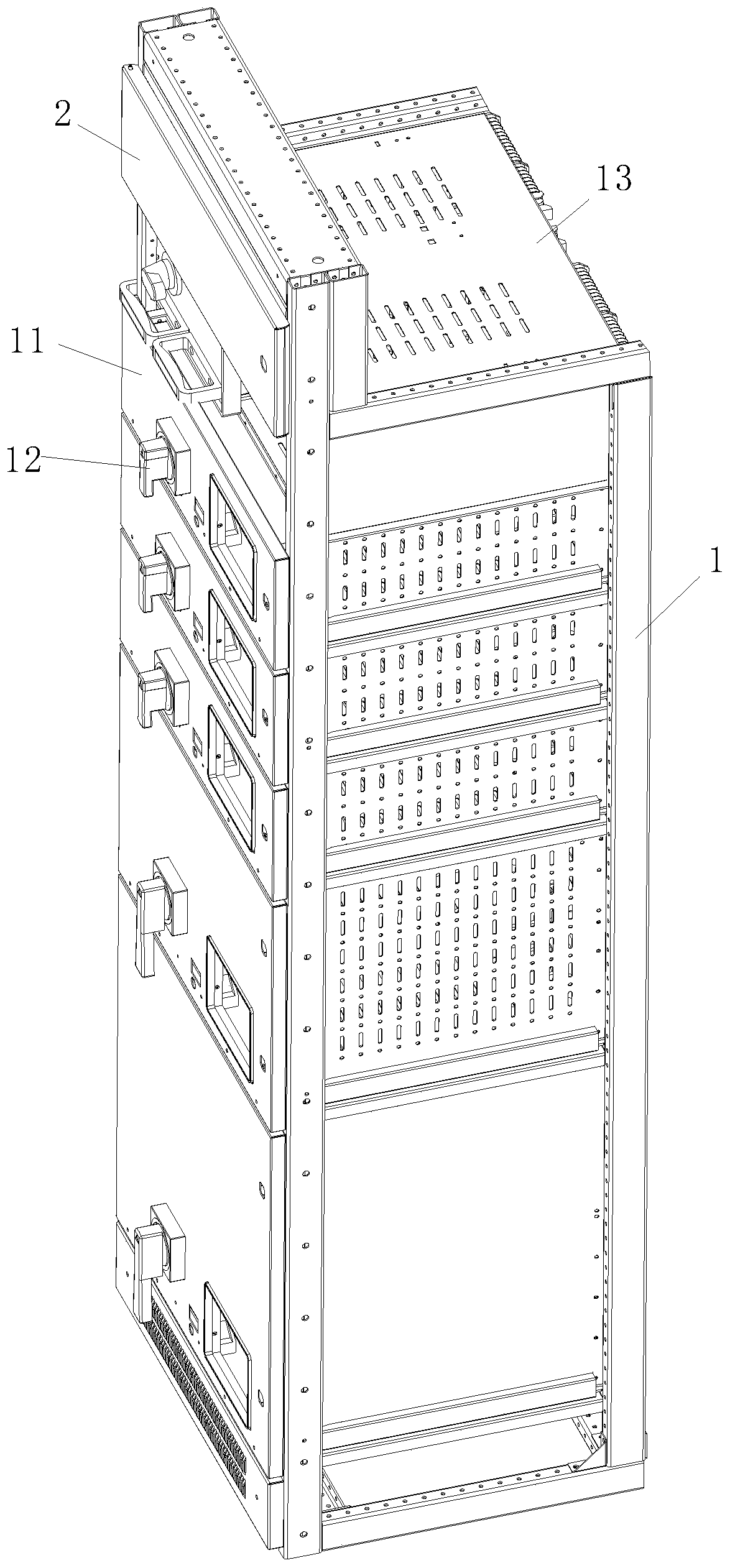
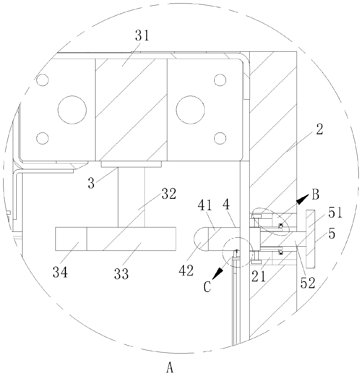
[0034] see Figure 1-6 As shown, a high and low voltage switch cabinet with a safety protection structure includes a cabinet body 1, a protective shell 2 is provided on the top of the cabinet body 1, and a back plate 11 is provided on the back side of the cabinet body 1. The board 11 is provided with a hook 12, the top and side walls of the cabinet 1 are provided with a ventilating board 13, the inside of the cabinet 1 is provided with a PLC controller 14, and the top of the cabinet 1 is provided with a protective shell 2....


PUM


Abstract

The invention discloses a high-low voltage switch cabinet with a safety protection structure and a working method of the high-low voltage switch cabinet. The cabinet comprises a cabinet body, a protective shell is arranged at the top of the cabinet body; a backboard is arranged on the back surface of the cabinet body; hooks are arranged on the backboard; ventilating plates are arranged at the topand on the side wall of the cabinet body; an electrifying mechanism is arranged below the pushing mechanism; and a power-off mechanism is electrically connected to one side of the power-on mechanism,the power-on mechanism and the power-off mechanism are both arranged in the protective shell, a clamping mechanism is arranged in the protective shell, a third inner groove located in one side of themovable rod mechanism is formed in the protective shell, and a clamping mechanism is installed in the third inner groove. Through cooperative use of the conductive mechanism and the power-off mechanism, the conductive mechanism and the power-off mechanism can be quickly closed or opened, the performance of quick power-on or quick power-off is achieved, and the safety performance of the switch cabinet can be effectively improved through quick power-off.

Description

technical field [0001] The invention belongs to the technical field of switch cabinets, and in particular relates to a high and low voltage switch cabinet with a safety protection structure and a working method thereof. Background technique [0002] The switch cabinet is a kind of electrical equipment. The outside line of the switch cabinet first enters the main control switch in the cabinet, and then enters the sub-control switch. Each branch is set according to its needs. Such as instruments, automatic controls, motor magnetic switches, various AC contactors, etc., some also have high-voltage room and low-voltage room switch cabinets, high-voltage busbars, such as power plants, etc. load shedding. [0003] The existing switchgear will generate heat or slow heat dissipation when it is in use, which will cause the temperature inside the switchgear to rise and affect the use. The safety protection mechanism inside the switchgear will cut off the power in time for the switchg...

Claims


Application Information

Patent Timeline
Patent Type & Authority Applications(China)
IPC IPC(8): H02B1/32H02H5/04
CPCH02B1/32H02H5/047
Inventor 张合生平亚玲
Owner ANHUI WANHUA ELECTRICAL TECHNOLOGY CO LTD
Learn More