No matter what type of encoder, it is necessary to additionally install a scale (grating or magnetic grid) on the motor body, which has disadvantages such as high cost, complicated installation, and difficult to control the size of the error.
[0003] In addition, the grating is easily affected by the environment such as
oil pollution and dust, so it is not suitable for application under harsh working conditions
The anti-
pollution ability of the magnetic grid is relatively good, but the magnetic grid is easily magnetized by the external
magnetic field, especially for small linear motors, the magnetic scale should be installed away from the magnetic steel on the
secondary side inside the motor, otherwise it will be magnetized and cause the encoder to fail
[0004] In addition, generally linear gratings or magnetic gratings are incrementally engraved and cannot provide absolute positions. Therefore, when applied to linear motors, they cannot provide primary phase information in the motor. When the linear motor is powered on for the first time, there will be primary Relatively large position movement is not allowed in many applications. In order to overcome this shortcoming, some motors are additionally equipped with a Hall phase sensor to sense the phase of the primary motor, which not only increases the complexity of wiring but also increases the cost.
[0005] In order to solve the shortcomings of linear encoders such as complex installation, high cost, susceptibility to
pollution, and the influence of magnetic fields, a
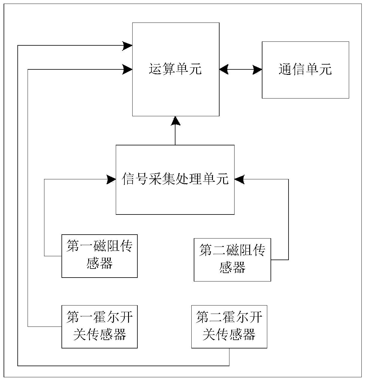
Chinese patent with publication number CN 106849520 A discloses a magnetic track encoder for linear motors, which includes a housing, and is installed in the housing There is a PCB board, wherein, the PCB board is provided with a Hall sampling circuit for collecting the
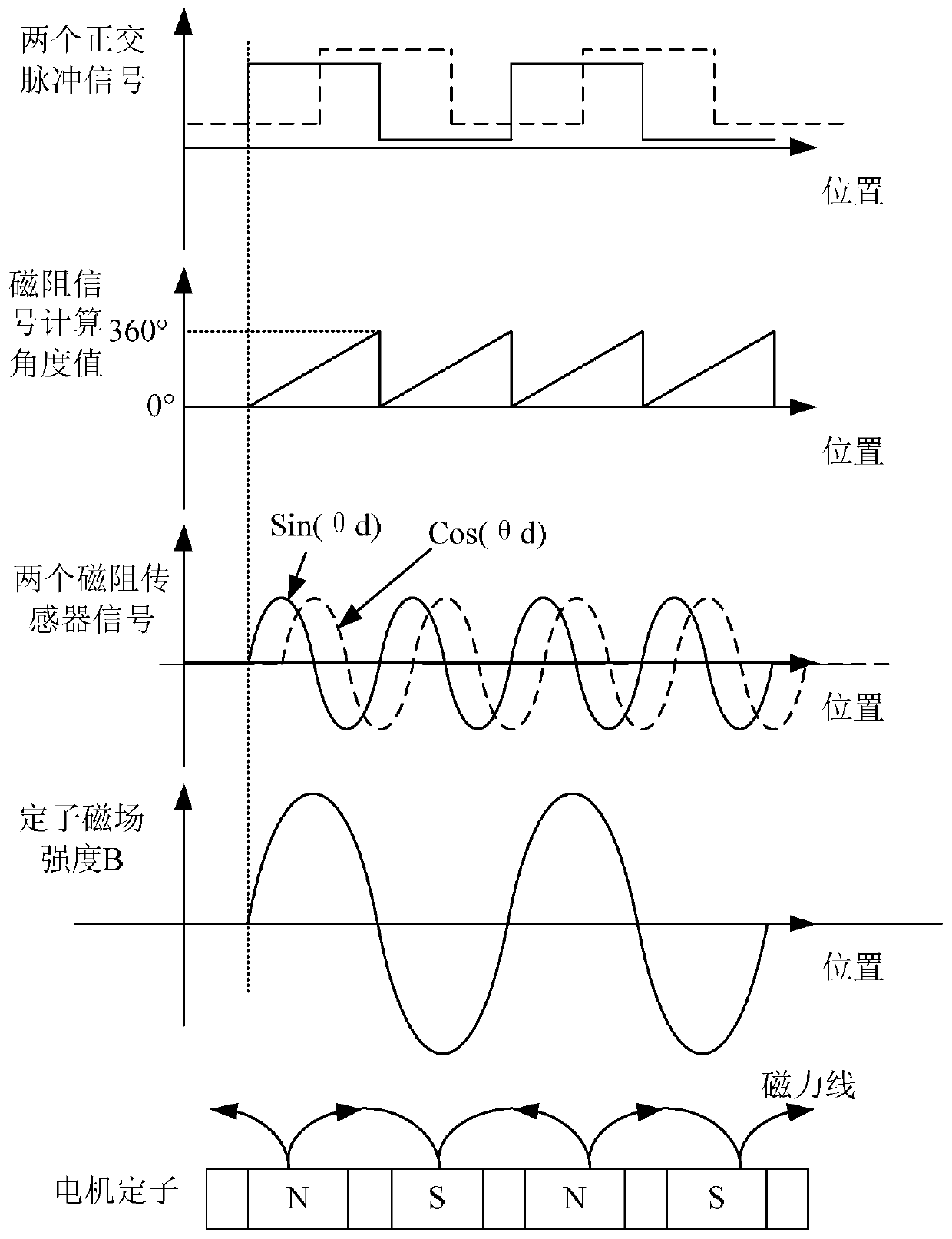
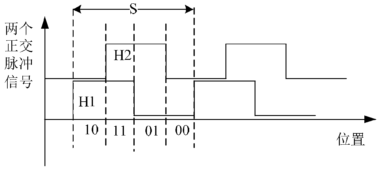
magnetic field signal generated by the primary during motion, and converting the magnetic field signal into two
voltage signals with a
phase difference of 90°; A
subdivision circuit for subdividing the two-way
voltage signals into preset multiples to obtain two-way orthogonal encoder signals; a differential signal conversion circuit for converting the two-way orthogonal encoder signals into differential signals, through the Huo The sampling circuit collects the magnetic field signal and converts it into a voltage signal. After subsequent
subdivision and differential signal conversion processing, accurate position data can be obtained.
In this structure, the Hall sampling circuit adopts the first Hall sensor and the second Hall sensor which can convert the magnetic field signal into a sine voltage signal and a cosine voltage signal respectively, and the first Hall sensor and the second Hall sensor must adopt linear The Hall sensor can obtain the
primary position data in the subsequent processing; however, the linear Hall sensor must work in the
linear range and has relatively strict requirements on the range of magnetic
field strength. Therefore, the use environment of the encoder is limited. Certain restrictions, and in order to avoid being affected, it must be equipped with a shielding case. In addition, after the encoder is installed, the requirements for the magnetic field consistency of the multiple magnets arranged in the secondary are also high, otherwise its accuracy will be greatly affected; However, in many cases, due to the magnetic field
magnetization accuracy of the secondary magnetic steel of the motor, there is often a certain physical deviation, and at the same time, there will be some large physical errors when the magnetic steel is installed. In these cases, the
absolute positioning of the encoder will be greatly reduced. precision
However, in some occasions that require high precision (printing,
machine tools,
semiconductor industries, etc.), it is necessary to compensate the motor encoder for full-
stroke accuracy, and the above encoders cannot meet the requirements.
Moreover, the above-mentioned encoder does not output the phase information obtained by the Hall sensor. The linear motor using this encoder will still have a relatively large
primary position shift when it is first powered on to find the phase. This is not true in many applications. Allowed

