High-speed dispersion machine for chemical engineering

A high-speed dispersing machine, chemical technology, applied to mixers with rotating stirring devices, mixers, mixer accessories, etc., can solve the problems of inconvenient removal of paint, unfavorable paint dispersion, etc., and achieve the effect of accelerating fluidity

Inactive Publication Date: 2020-09-01
ZHONGSHAN DONGWANGYANG CHEM
View PDF7 Cites 0 Cited by
  • Summary
  • Abstract
  • Description
  • Claims
  • Application Information

AI Technical Summary

Problems solved by technology

The device disperses the paint through the reverse rotation of the stirring blade and the stirring rod, which can achieve the dispersion effect, but the paint is added at one time, which is not conducive to the dispersion of the paint, and the dispersed paint is inconvenient to take out

Method used


Image

  • High-speed dispersion machine for chemical engineering
  • High-speed dispersion machine for chemical engineering
  • High-speed dispersion machine for chemical engineering

Examples


Embodiment 1

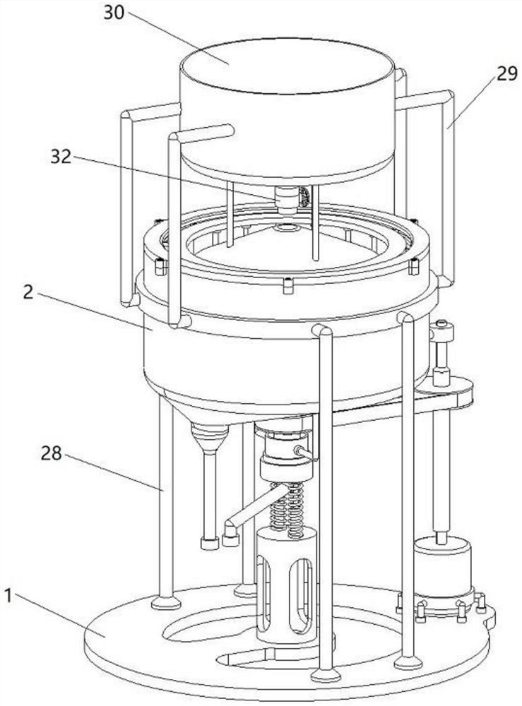
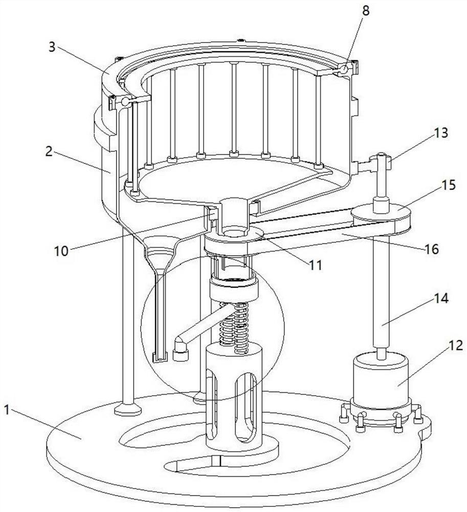
[0030] A high-speed dispersing machine for chemical industry, such as Figure 1-Figure 4 As shown, it includes a support frame 1, a funnel-shaped cylinder 2, a dispersion mixing assembly, a power assembly and a feeding assembly. The dispersing and mixing assembly for dispersing and mixing materials in a rotating manner, the power assembly powered by a motor for rotation is provided on the rear side of the support frame 1, and the unloading assembly is provided below the dispersing and mixing assembly for unloading through a pipeline.

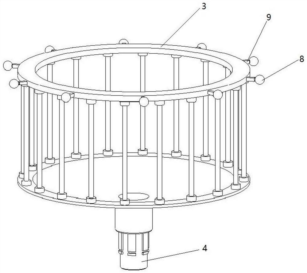
[0031] Such as figure 2 , image 3 , Figure 6 , Figure 7 and Figure 12 As shown, the dispersion mixing assembly includes an annular frame 3, a liquid outlet pipe 4, a sliding ball fixing ring 6, a sliding ball 8, a connecting rod 9, and a bearing 10. The top of the funnel-shaped cylinder 2 is provided with a first semicircular sliding groove 5, and the funnel A sliding ball fixing ring 6 is installed on the top of the type cylinder 2, a...

Embodiment 2

[0039] On the basis of Example 1, such as image 3 , Figure 4 , Figure 8 , Figure 9 , Figure 10 , Figure 11 and Figure 12 As shown, it also includes a liquid outlet support 19, a filter frame 20, a support column 21, a lifting pipe 22, a liquid outlet frame 23, a second cover 24, a liquid outlet inclined pipe 25, a lifting rod 26, a spring 27, and a funnel The bottom of the type cylinder 2 is suspended and welded with a liquid outlet bracket 19, a filter frame 20 is installed below the liquid outlet bracket 19, a liquid outlet frame 23 is installed below the filter frame 20, and a lifting rod 26 and a lifting rod 26 are welded below the liquid outlet frame 23. Liquid outlet inclined pipe 25, the end of liquid outlet inclined pipe 25 is equipped with a second cover 24, support column 21 is equipped with on the support frame 1, is welded with lifting pipeline 22 on the support column 21, between lifting pipeline 22 and lifting rod 26 Spring 27 is housed between.

[00...


PUM


Abstract

A high-speed dispersion machine for chemical engineering comprises a supporting frame, a funnel-shaped cylinder, a dispersing and mixing assembly, a power assembly and a discharging assembly. The funnel-shaped cylinder is installed on the supporting frame, and a first semicircular sliding groove is formed in the top of the funnel-shaped cylinder; the dispersing and mixing assembly is mounted in the funnel-shaped cylinder and is used for dispersing and mixing materials in a rotating manner; the power assembly is installed on the supporting frame and is powered by a motor to rotate; and the discharging assembly is installed on the dispersing and mixing assembly and conducts discharging through a pipeline. Through the annular frame, when raw materials are dispersed and mixed, the flow of theraw materials is accelerated, so that the raw materials can be better and faster mixed; and the raw materials can be rapidly taken out through a cover, the discharging speed can be controlled by controlling a discharging valve, the raw materials can be better dispersed and mixed, the materials fall on a conical block when falling down, the raw materials are dispersed, and therefore later-period dispersing and mixing of the materials are facilitated.

Description

technical field [0001] The invention relates to a high-speed disperser for chemical industry, in particular to a high-speed disperser for chemical industry. Background technique [0002] When producing paint, paint raw materials need to be mixed with other materials. [0003] The patent authorization announcement number is CN208413029U, which discloses a high-speed dispersing machine for paint processing, including a base body, a cavity, a support rod, a housing, a lifting device, a transmission mechanism, a stirring shaft, a material bucket, a rotating shaft, and a driving motor. Fixing devices and partitions, a cavity is opened in the middle of the base body, and a lifting device is placed in the cavity. The lifting device is connected to the bottom of the housing through a lifting rod at the upper end, and is supported by a support rod. The rod is arranged on the bosses on both sides of the upper part of the base body, and is slidably connected along the bosses. The set...

Claims


Application Information

Patent Timeline
Patent Type & Authority Applications(China)
IPC IPC(8): B01F7/32B01F15/02B01F27/96
CPCB01F27/96B01F35/71805B01F2101/30
Inventor 唐龙珠
Owner ZHONGSHAN DONGWANGYANG CHEM
Why Eureka
Try Eureka