
Directional cutting device for wood floor processing and working method thereof

A cutting device and wood technology, applied in the direction of transportation and packaging, conveyors, conveyor objects, etc., can solve the problems of damaged cutting surface of wooden floor, low work efficiency, large space occupied by machinery, etc.

Inactive Publication Date: 2020-09-01
安徽阜南县向发工艺品有限公司
View PDF5 Cites 2 Cited by
  • Summary
  • Abstract
  • Description
  • Claims
  • Application Information

AI Technical Summary

Problems solved by technology

[0003] One of the processing bases of wooden floors is to cut and process the formed formwork to a preset size, but in the prior art, when cutting and processing wooden floors, on the one hand, it is necessary to transfer batches of wooden floors To the cutting table, on the other hand, it is necessary to transfer the single wooden floor to the cutting device for cutting, so that two kinds of transfer devices are needed to transfer the wooden floor, which will cause the machine to take up a lot of space and work efficiency is low. And when cutting, affected by the cutting device on the cutting surface, it is easy to cause damage to the cutting surface of the wooden floor. In order to solve the above problems, the present invention provides the following technical solutions

Method used


Image

  • Directional cutting device for wood floor processing and working method thereof
  • Directional cutting device for wood floor processing and working method thereof
  • Directional cutting device for wood floor processing and working method thereof

Examples


Embodiment Construction

[0027] The technical solutions in the embodiments of the present invention will be clearly and completely described below. Obviously, the described embodiments are only some of the embodiments of the present invention, but not all of them. Based on the embodiments of the present invention, all other embodiments obtained by persons of ordinary skill in the art without creative efforts fall within the protection scope of the present invention.

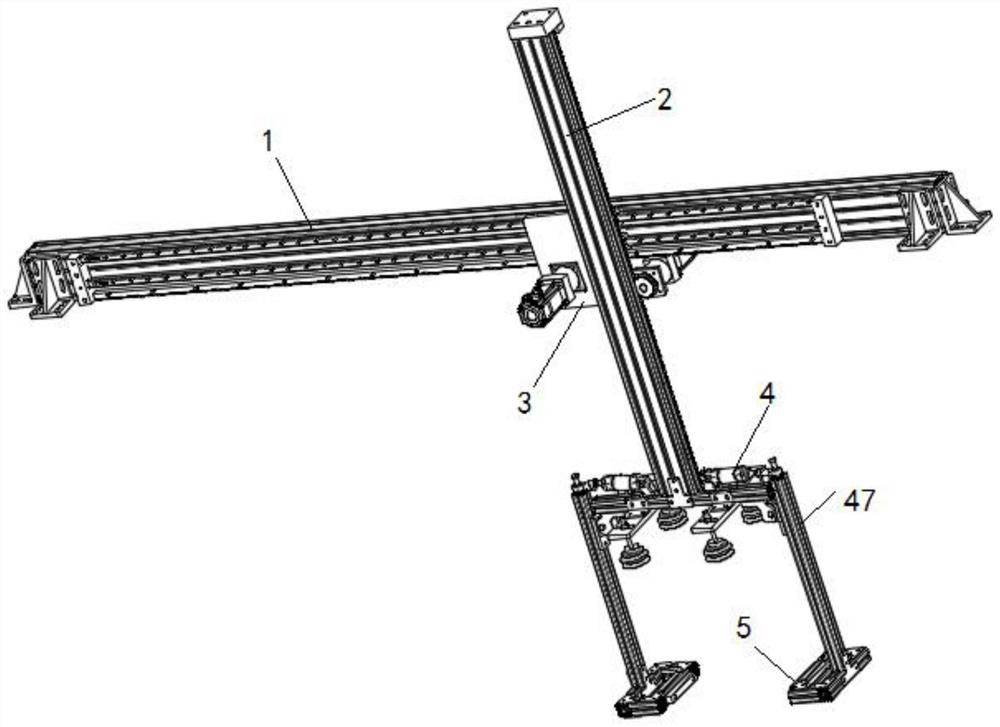
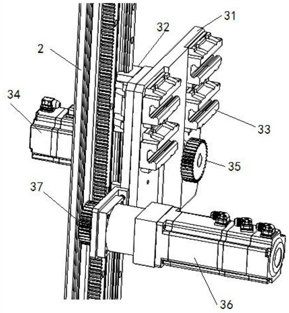
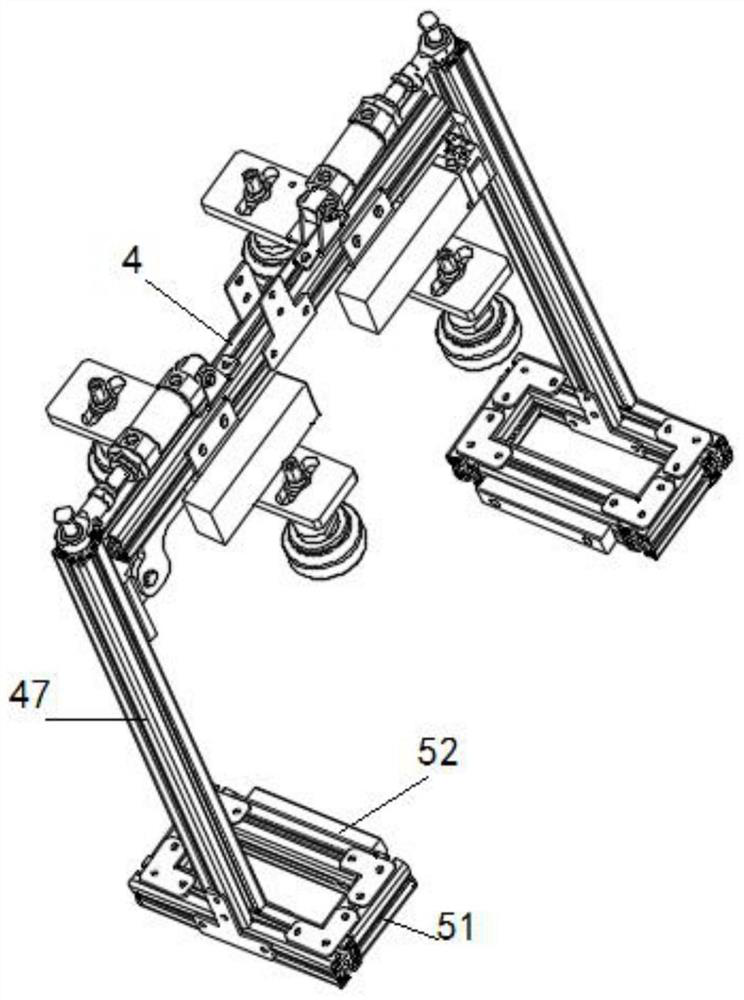
[0028] A directional cutting device for wood floor processing, such as Figure 1 to Figure 4 As shown, it includes a horizontal beam 1, a transfer device 3 slidably installed on the horizontal beam 1, a vertical beam 2 slidably installed on the transfer device 3, a running device 4 fixedly installed at one end of the vertical beam 2, and a fixed installation on the The clamping frame 5 on the running device 4;

[0029] The transfer device 3 includes a fixed mounting plate 31, a first slider 32 is fixedly installed on one side of the fix...


PUM


Abstract

The invention discloses a directional cutting device for wood floor processing and a working method thereof. The directional cutting device comprises a transverse beam, a transfer device slidably mounted on the transverse beam, a vertical beam slidably mounted on the transfer device, a running device fixedly mounted at one end of the vertical beam, and a clamping frame fixedly mounted on the running device; and according to the directional cutting device for wood floor processing and the working method thereof, in the whole process, the transfer of batch wooden floors and single wooden floorscan be realized at the same time, the problems that the stricture is complex and the occupying space is large due to the fact that dividing two transfer devices are required to realize transfer in thetraditional technology are avoided, cutting is carried out through the fixation of a suction cup, the integrity of a cutting surface is ensured, and the wooden floors after cutting can be timely transferred.

Description

technical field [0001] The invention belongs to the technical field of wooden floor processing, and in particular relates to a directional cutting device for wooden floor processing and a working method thereof. Background technique [0002] Floor, that is, the surface layer of the ground or floor of the house, is made of wood or other materials. There are many classifications of floors. According to the structure, they are: solid wood floor, reinforced composite wood floor, three-layer solid wood composite floor, bamboo wood floor, anti-corrosion Flooring, cork flooring and the most popular multi-layer solid wood composite flooring, etc.; classified by use: household, commercial, anti-static flooring, outdoor flooring, special flooring for stage dance, special flooring for sports halls, special flooring for track and field, etc.; The classification of environmental protection grades includes: E0 grade floor, E1 grade floor, F4 grade floor, JAS star standard F4 star floor, e...

Claims


Application Information

Patent Timeline
IPC IPC(8): B65G47/90B65G47/91
CPCB65G47/90B65G47/91B65G2201/0282
Inventor 王登位赵金红杨大雷
Owner 安徽阜南县向发工艺品有限公司
Learn More