Water purifying device with efficient filtering function
A water purification device and high-efficiency filtration technology, which is applied in the field of water purification and filtration equipment and high-efficiency filtration water purification devices, can solve the problems of inconvenient loading and unloading of filter elements, complex structure, and poor filtering effect, and achieve a structure that does not occupy space, is small in size, The effect of easy connection
Active Publication Date: 2020-09-01
山东世韩环保工程有限公司
11 Cites 0 Cited by
AI-Extracted Technical Summary
Problems solved by technology
[0004] Based on the above technical problems, the present invention provides a water purification device for high-efficiency filtration, thereby solving the technic...
Method used
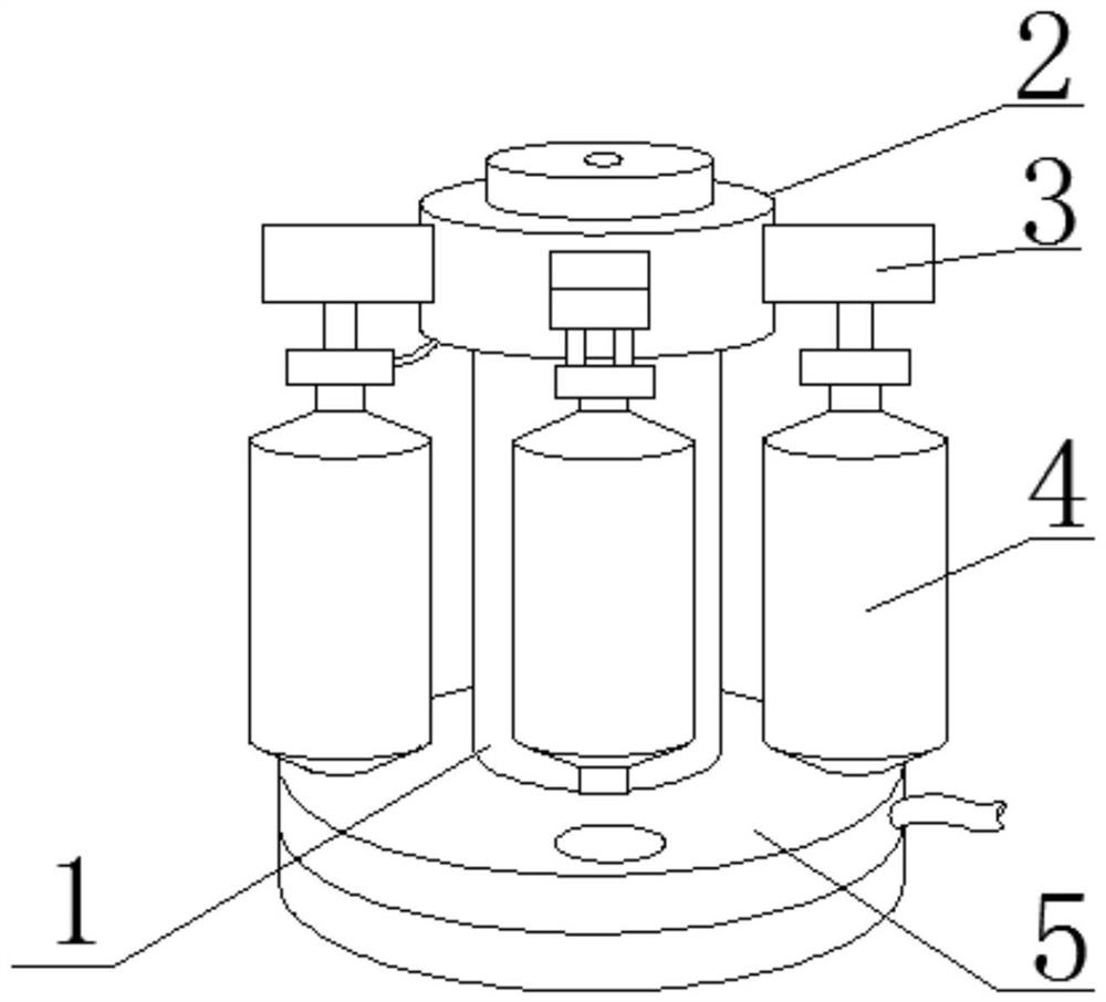
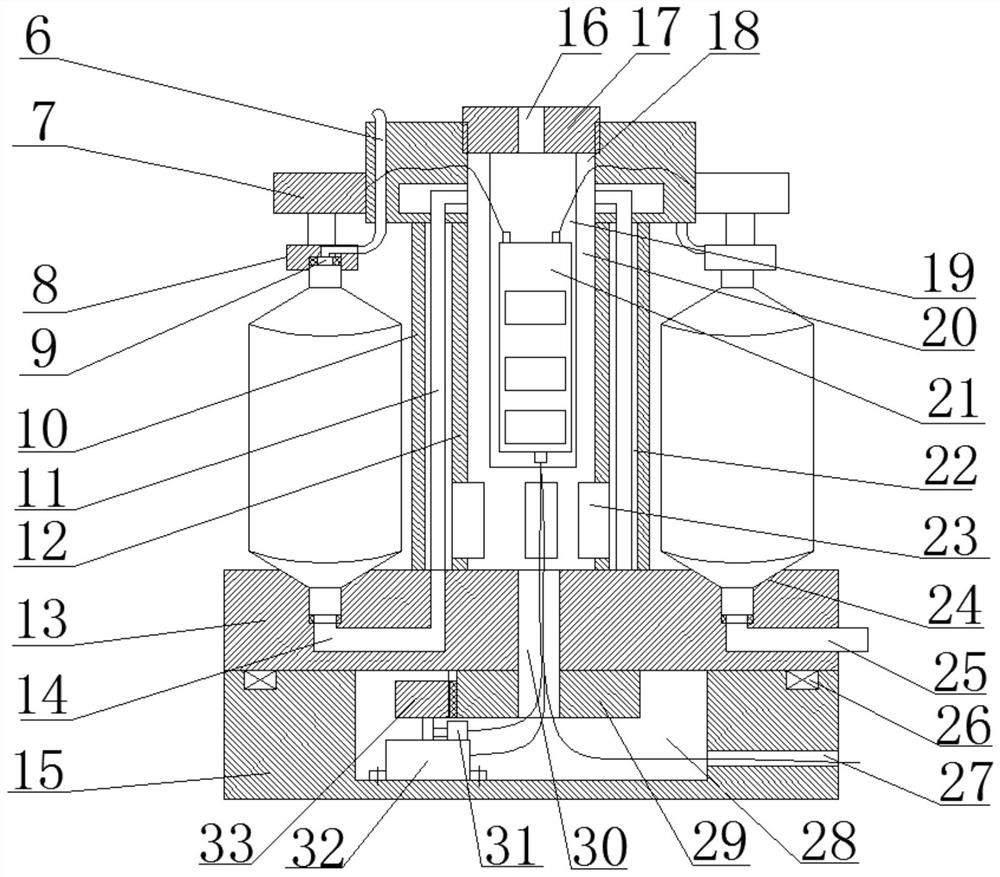
As shown in Figure 1 and Figure 2, this water purifier multi-stage filter element group comprises a sleeve 1 at least, and sleeve 1 can adopt stainless steel, carbon steel, alloy steel etc. to make, to guarantee its intensity and service life , and can prevent embroidery corrosion, the top plate 2 and the bottom plate 5 are fixedly connected to the two ends of the sleeve 1, the material of the top plate 2 and the bottom plate 5 can be the same material as the sleeve 1, in order to reduce the area, the top plate 2 and the bottom plate 5 are preferably round Disc-shaped structure, between the top plate 2 and the bottom plate 5 is provided with a filter cartridge assembly 4, the filter cartridge assembly 4 is provided with multiple stages, and the multi-stage filter cartridge assemblies 4 are connected in series through pipelines to form a multi-stage filter structure , and in order to further reduce the volume of the multi-stage filter element group, the multi-stage filter cartridge assembly 4 is arranged on the outside of the sleeve 1 in a ring shape with the sleeve 1 as the center, thereby forming a circular multi-stage filter structure as a whole.
Based on above-mentioned water purifier multi-stage filter core group, filter cartridge assembly 4 is annularly arranged between top plate 2 and base plate 5 and is designed around sleeve 1 circumference, makes multi-stage filter core group integral structure compact, volume is small, and The filter cartridge assembly 4 is provided with multiple stages, with high filtration efficiency and good effect. The filter cartridge assembly 4 is compressed by the pressing device 3, the connection is firm, and it is easy to assemble and disassemble. The water delivery pipeline 11 between the filter cartridge assemblies 4 passes through the sleeve 1 The internal piping realizes the pipeline connection between the upper and lower ports of the filter cartridge assembly 4. The pipeline design is reasonable, and through the internal piping, it will not be exposed to the outside, and the pipeline protection is better. The filter cartridge assembly is driven by the rotatable upper rotating plate 13 4 rotation, and then the filter cartridge assembly 4 can be rotated to any position, which can facilitate the loading and unloading of the filter cartridge assembly 4.
Concrete, inner tube 12 and outer tube 10 are cylindrical, and the cavity of inner tube 12 inside 12 is then used as electrical device installation cavity 20, is provided with fixed plate 19 in the electrical device installation cavity 20, and this fixed The control circuit board 21 is fixed on the board 19, and in order to facilitate the loading and unloading of the fixed board 19 and the control circuit board 21, the middle part of the top plate 2 is provided with a mounting hole 18 communicating with the electrical device mounting cavity 20, and the upper end of the mounting hole 18 is located at the same position. A compression cover 17 is threadedly connected, and the above-mentioned fixing plate 19 is connected to the lower end of the compression cover 17, so that the internal fixing plate 19 and the control circuit board 21 can be lifted out by using the compression cover 17, and quick loading and unloading of the two can be realized Further, the middle part of the upper rotating plate 13 is provided with a lower wiring hole 30 that runs through the gear teeth 29, and the lower wiring hole 30 communicates the electrical device installation cavity 20 with the installation cavity 28, and the circuit of the rotating motor 32 and the contact angle sensor 31 The wires extend into the electrical device installation cavity 20 through the lower wiring hole 30 and are electrically connected to the control circuit board 21 through the plug, and the circuit wires of the electric push rod 7 penetrate the top plate 2 and then extend into the electrical device installation cavity 20 and pass through the same. The plug is electrically connected to the control circuit board 21, so that the above-mentioned electrical devices can be electrically connected to the control circuit board 21 through the circuit, and control or signal transmission can be realized through the control circuit board 21, and the inner cylinder 12 is ...
Abstract
The invention discloses a water purifying device with an efficient filtering function. The device comprises a cylindrical shell and a top cover detachably connected to the top of the cylindrical shell, a tap water inlet pipe through hole is formed in the circumferential surface of the upper end of the cylindrical shell, a water outlet pipeline through hole and a main line through hole are formed in the circumferential surface of the lower end of the cylindrical shell, an access hole is further formed in the middle of the cylindrical shell, an access door is arranged at the access hole, and theaccess door can be rotated into the cylindrical shell or rotated out of the cylindrical shell to seal the access hole; and a water purifier multi-stage filter element group is fixed in the cylindrical shell, the water purifier multi-stage filter element group comprises a top plate, a bottom plate and a sleeve connected between the top plate and the bottom plate, and a filter cartridge assembly isalso arranged between the top plate and the bottom plate. The device adopts a circular design as a whole, is small in structure, saves space, is extremely convenient to assemble, disassemble and maintain, is flexible in filter element arrangement number and type, and can improve the filter efficiency, quality and effect of the filter element as partition plates are arranged in the filter elementto form a water diversion assembly.
Application Domain
Water/sewage treatment by irradiationSpecific water treatment objectives +5
Technology Topic
Water purification filterStructural engineering +4
Image
Examples
- Experimental program(1)
Example Embodiment
[0032] The technical solutions in the embodiments of the present invention will be clearly and completely described below in conjunction with the accompanying drawings in the embodiments of the present invention. Obviously, the described embodiments are only a part of the embodiments of the present invention, rather than all the embodiments.
[0033] In the description of the present invention, it should be understood that the terms "one end", "the other end", "both ends", "between", "middle", "lower", "upper", "lower", etc. indicate The orientation or positional relationship is based on the orientation or positional relationship shown in the drawings, which is only for the convenience of describing the present invention and simplifying the description, and does not indicate or imply that the device or element referred to must have a specific orientation, be constructed in a specific orientation, and Operation, therefore cannot be understood as a limitation of the present invention.
[0034] In the description of the present invention, it should be noted that, unless otherwise clearly specified and limited, the terms "set" and "connection" should be understood in a broad sense, for example, it can be a fixed connection, a detachable connection, or an integral Ground connection; it can be directly connected or indirectly connected through an intermediary. For those of ordinary skill in the art, the specific meaning of the above-mentioned terms in the present invention can be understood in specific situations.
[0035] First of all, this embodiment first describes in detail the core component of the high-efficiency filtration water purifier-the multi-stage filter element group of the water purifier.
[0036] figure 1 The three-dimensional schematic diagram of the multi-stage filter element group of the water purifier shown in this embodiment; figure 2 It is a schematic diagram of the cross-sectional structure of the multi-stage filter element group of the water purifier shown in this embodiment.
[0037] Such as figure 1 with figure 2 As shown, the multi-stage filter element set of the water purifier includes at least a sleeve 1. The sleeve 1 can be made of stainless steel, carbon steel, alloy steel, etc., to ensure its strength and service life, and to prevent embroidery from corrosion. The two ends of the cylinder 1 are fixedly connected with a top plate 2 and a bottom plate 5. The top plate 2 and the bottom plate 5 can be made of the same material as the sleeve 1. In order to reduce the area, the top plate 2 and the bottom plate 5 should preferably adopt a disc-shaped structure. The bottom plate 5 is provided with a filter cartridge assembly 4, the filter cartridge assembly 4 is provided with multiple stages and the multi-stage filter cartridge assemblies 4 are connected in series through pipelines to form a multi-stage filter structure, and to further reduce the multi-stage filter element group Volume, the multi-stage filter cartridge assembly 4 is annularly arranged outside the sleeve 1 with the sleeve 1 as the center, thereby forming a circular multi-stage filter structure as a whole.
[0038] Necessarily, as the upper end pressing structure of the filter cartridge assembly 4, the outer side of the lower end of the top plate 2 is provided with a plurality of pressing devices 3 in a ring shape, and the pressing devices 3 are used for one-to-one correspondence with the filter cartridge assembly 4 and compress the filter cartridge assembly 4. Thus, the filter cartridge assembly 4 is pressed between the top plate 2 and the bottom plate 5. Specifically, the pressing device 3 includes an electric push rod 7. The main body of the electric push rod 7 is fixed to the outside of the top plate 2, and the electric push rod 7 It is arranged vertically, and the push rod end at the lower end is connected with a gland 8 which is used to compress the upper water inlet of the filter cartridge assembly 4. In order to ensure the pressing effect, a compression groove is provided at the lower end of the gland 8 9. During compression, the upper water inlet of the filter cartridge assembly 4 is positioned in the compression groove 9 and the upper water inlet of the filter cartridge assembly 4 is compressed and sealed as a whole through the gland 8. The gland 8 is also provided with One end of the water delivery pipe 11 is connected to the lower water outlet of the upper stage filter cartridge assembly 4, and the water delivery pipe 11 of the filter cartridge assembly 4 at the first stage is connected to the tap water inlet pipe 6 that penetrates the top plate 2. The water inlet pipe 6 communicates with the external tap water supply system to supply water to the entire filter element group.
[0039] In the above structure, the bottom plate 5 is set up as an upper rotating plate 13 and a lower fixing plate 15 arranged up and down. The upper rotating plate 13 serves as the lower end positioning structure of the filter cartridge assembly 4, and the upper rotating plate 13 is provided with a plurality of positions in a ring shape. Hole 24. The positioning hole 24 is used to position the lower end of the filter cartridge assembly 4, which can press the lower water outlet of the multi-stage filter cartridge assembly 4 in the positioning hole 24 in turn under the action of the pressing device 3 and seal it. In order to facilitate the series connection of the filter cartridge assembly 4, a pipe hole 14 is provided in the upper rotating plate 13, and the above-mentioned water delivery pipe 11 passes through the sleeve 1 and the pipe hole 14 and exits from the lower part of the upper level filter cartridge assembly 4. The water outlet is connected, and the lower water outlet of the filter cartridge assembly 4 of the last stage is connected to a water outlet pipe 25 that penetrates the upper rotating plate 13, and the water outlet pipe 25 extends out of the upper rotating plate 13 or communicates with an external water outlet pipe system. Further, a sealing ring is arranged in the pressing groove 9 and the positioning hole 24. When the filter cartridge assembly 4 is compressed, the sealing ring is squeezed to seal the upper water inlet and the lower water outlet of the filter cartridge assembly 4.
[0040] Furthermore, the above-mentioned lower fixing plate 15 is mainly used to support the upper rotating plate 13, and a mounting cavity 28 is formed in the inner part of the mounting cavity 28. A rotating motor 32 is fixed in the mounting cavity 28. The output shaft of the rotating motor 32 is connected with a driving gear 33. Gear teeth 29 are provided in the middle of the lower end of the upper rotating plate 13. The driving gear 33 meshes with the gear teeth 29 to drive the upper rotating plate 13 to rotate horizontally, so that the rotating motor 32 is used to rotate to drive the upper rotating plate 13, sleeve 1, filter cartridge assembly 4 and the top plate 2 are rotated, so that the filter cartridge assembly 4 that needs to be replaced and overhauled can be rotated to the inspection position or the inspection port of the water purifier, which is convenient for loading and unloading the filter cartridge assembly 4. After the filter cartridge assembly 4 is replaced and filled, use the pressing device 3 Press the replaced filter cartridge assembly 4 tightly and rotate it in the reverse direction to the original position. Further, the upper end surface of the lower fixing plate 15 is provided with a bearing groove 26, and a ball bearing is provided in the bearing groove 26, so that the use of the ball bearing can improve the rotation effect of the upper rotating plate 13;
[0041] Based on the above-mentioned water purifier multi-stage filter element group, the filter cartridge assembly 4 is arranged in a ring shape between the top plate 2 and the bottom plate 5 and is designed around the circumference of the sleeve 1, so that the multi-stage filter element assembly has a compact overall structure and small volume, and the filter cartridge assembly 4 Set up multiple stages, with high filtration efficiency and good effect. The filter cartridge assembly 4 is compressed by the pressing device 3, the connection is firm, and the assembly and disassembly is convenient. The water delivery pipeline 11 between the filter cartridge assembly 4 runs through the inside of the sleeve 1 , To realize the pipeline connection between the upper and lower ports of the filter cartridge assembly 4, the pipeline design is reasonable, and through the internal pipe, it will not be exposed to the outside, and the pipeline protection is better. The filter cartridge assembly 4 is driven to rotate through the rotatable upper rotating plate 13. Furthermore, the filter cartridge assembly 4 can be rotated to any position, which facilitates the loading and unloading of the filter cartridge assembly 4.
[0042] In order to precisely control the rotation position of the filter cartridge assembly 4 and make it rotate to the required inspection position or inspection port, the above-mentioned water purifier multi-stage filter element group is also provided with a contact angle sensor 31 in the installation cavity 28, and a contact angle sensor 31 The detection end of the contact angle sensor 31 is in contact with the output shaft of the rotating motor 32, and the contact angle sensor 31 can be used to detect the linear velocity of the rotating motor 32 to obtain the rotation angle of the upper rotating plate 13 at a specific time, thereby obtaining the rotation angle of the specific filter cartridge assembly 4 .
[0043] In order to facilitate the running of the water pipeline 11, the above-mentioned sleeve 1 includes an inner tube 12 and an outer tube 10 coaxially sleeved. The diameter of the inner tube 12 and the outer tube 10 are different, so that the inner tube 12 and the outer tube 10 are different in diameter. A running lumen 22 for running pipes can be formed. The water delivery pipeline 11 can realize pipeline communication between the top plate 2 and the bottom plate 5 through the running lumen 22. The water delivery pipe 11 will not be exposed, and the pipeline structure is simple and reasonable , And will not cause pipe winding or mixing.
[0044] Specifically, the inner cylinder 12 and the outer cylinder 10 are both cylindrical, and the cavity inside the inner cylinder 12 is used as the electrical device mounting cavity 20. The electrical device mounting cavity 20 is provided with a fixing plate 19 on which The control circuit board 21 is fixed, and in order to facilitate the assembly and disassembly of the fixing board 19 and the control circuit board 21, the middle of the top plate 2 is provided with a mounting hole 18 communicating with the electrical component mounting cavity 20, and the upper end of the mounting hole 18 is also screwed with The compression cover 17, the above-mentioned fixing plate 19 is connected to the lower end of the compression cover 17, so that the internal fixing plate 19 and the control circuit board 21 can be lifted out by using the compression cover 17, and the two can be quickly assembled and disassembled; , The middle of the upper rotating plate 13 is provided with a lower wiring hole 30 penetrating the gear teeth 29, the lower wiring hole 30 connects the electrical component mounting cavity 20 with the mounting cavity 28, and the circuit lines of the rotating motor 32 and the contact angle sensor 31 pass The lower wiring hole 30 extends into the electrical device installation cavity 20 and is electrically connected to the control circuit board 21 through a plug. The circuit line of the electric push rod 7 penetrates the top plate 2 and then extends into the electrical device installation cavity 20 and is also connected to the control via the plug The circuit board 21 is electrically connected, so that the above-mentioned electrical devices can be electrically connected to the control circuit board 21 through lines, and can be controlled or signal transmitted through the control circuit board 21, and the inner cylinder 12 is used to lay out the electrical devices, and the outer cylinder 10 is arranged The water conveying pipeline 11 runs through the pipe, so that the two can be separated, the water insulation effect of the electrical device can be ensured, and the overall safety of the device can be improved. Furthermore, the side wall of the lower fixing plate 15 is also provided with a bus hole 27. The bus hole 27 communicates with the electrical device mounting cavity 20 through the mounting cavity 28, and the circuit lines and signal lines of the control circuit board 21 are routed through the bus hole 27. .
[0045] In order to increase the purification and sterilization effect of the multi-stage filter element group, the lower end of the inner cylinder 12 of this embodiment is also provided with a plurality of ultraviolet sterilization lamps 23 in a ring shape, and the plurality of ultraviolet sterilization lamps 23 are partially (or all) extended. Out to the lumen 22, and the water delivery pipeline 11 or the water delivery pipeline 11 located in the lumen 22 adopts a transparent plastic tube or a plexiglass tube. In this way, the ultraviolet sterilization lamp 23 can counteract the water flowing through the water delivery pipeline 11 Sterilization of the medium can improve the quality of purified water, and can also effectively reduce bacteria and fungi that grow due to the filter element not being replaced for a long time.
[0046] On the basis of the above structure, the lower end of the filter cartridge assembly 4 forms a tapered surface protruding outward, and the upper end of the positioning hole 24 forms a conical platform that matches the tapered surface. When the filter cartridge assembly 4 is compressed by the pressing device 3 Then, the tapered surface of the lower end of the filter cartridge assembly 4 matches the cone, which can improve the degree of adhesion between the filter cartridge assembly 4 and the positioning hole 24, and improve the positioning effect. At the same time, the tapered surface and the cone are attached. Can be used as a sealing surface to strengthen the seal.
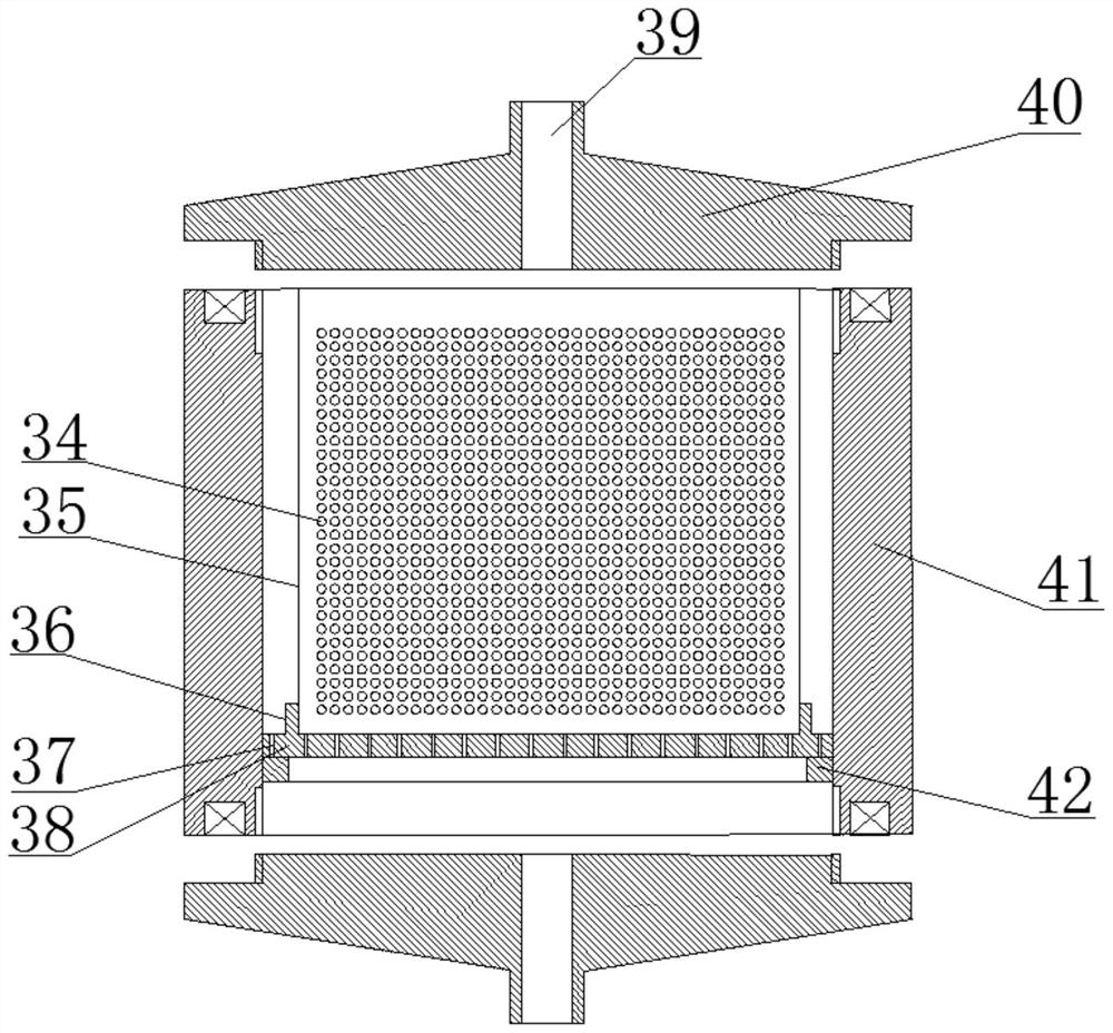
[0047] image 3 It is a schematic diagram of the structure of the filter cartridge assembly shown in this embodiment.
[0048] Such as image 3 As shown, for the better realization of the above-mentioned multi-stage filter element set of the water purifier, this embodiment also discloses a specific filter cartridge assembly 4, the filter cartridge assembly 4 at least includes a cylinder 41, and inner ports at both ends of the cylinder 41 The position is provided with an internal thread, and a cover body 40 is also provided at both ends of the cylinder body 41. The cover body 40 is provided with an external thread. The cylinder body 41 and the cover body 40 are detachably connected through the internal thread and the external thread. The middle of the cover 40 is formed with an upper water inlet 39 or a lower water outlet communicating with the inside of the cylinder 41. A positioning step 42 is provided inside the cylinder 41. A water permeable plate 38 with a plurality of water permeable holes 37 is placed on the positioning step 42. The pore size of the water permeable hole 37 is 0.3-0.5mm, and the middle of the upper end of the water permeable plate 38 is convexly formed with a positioning ring 36. In the positioning ring 36, a filter cartridge 35 is positioned and can be clamped inside. Specifically, The filter cartridge 35 is in the shape of a cylinder with open ends. A number of micropores 34 are provided on the circumferential surface of the filter cartridge 35. The pores 34 have a diameter of 0.1 to 0.3 mm and are located on the inner and outer circumferential surfaces of the filter cartridge 35. Ultrafiltration membranes are attached, and filter cartridges 35 are filled with filter elements. The filter cartridge assembly 4 connects the filter cartridge 35 through the two ends cover 40 and the filter element is positioned and clamped in the filter cartridge 35. The upper water inlet of the filter cartridge assembly 4 is connected to the filter cartridge 35 through the upper water inlet 39 of the upper cover 40 The water to be purified is filtered by the filter element and ultrafiltration membrane and then leaks from the permeable plate 38, and finally enters the water delivery pipe 11 or the water outlet through the lower water outlet of the lower cover 40. This embodiment uses a filter element and an ultrafiltration membrane to effectively remove most of the particles, suspended matter, mud, bacteria, suspended matter, viruses, heavy metals, solid soluble matter, polluted organic matter, calcium and magnesium ions, etc. in the water, and the filter element is used as the first The first-level filter medium, the inner and outer two-layer ultrafiltration membranes are used as the second and third-level filter media, so that the substances to be filtered in the water can be filtered in layers, and the filtering effect is good. The ultrafiltration membrane adopts both inner and outer sides. The micropores that pass between the two can slow down the speed of water passing through the two, extend the water generation time, increase the water filtration time, and further improve the filtration effect. The pores 34 of the filter cartridge 35 are larger than the membrane pores of the ultrafiltration membrane. It can avoid the formation of concentrated water due to the small space between the inner and outer membranes, and it will not squeeze the water through the ultrafiltration membrane due to the high pressure in the micropores, which improves the filtering effect.
[0049] In order to improve the filtering effect, the aforementioned filter element can be one or any combination of particulate carbon filter element, compressed carbon filter element, activated carbon filter element, polypropylene fiber cotton filter element, resin particulate filter element, particulate carbon filter element, compressed carbon filter element, activated carbon filter element, poly The propylene fiber cotton filter element and the resin particle filter element have different filtering characteristics and characteristics. According to the needs, each filter cartridge assembly 4 can be filled with the same or different filter elements, or each filter cartridge assembly 4 can be filled with more Different kinds of filter cartridges are filled.
[0050] Figure 4 It is a schematic diagram of the structure of the grid-shaped water diversion assembly shown in this embodiment.
[0051] Such as Figure 4 As shown, in order to further improve the filtering effect, the above-mentioned filter cartridge 35 is also provided with a horizontal partition 44 and a longitudinal partition 43. The horizontal partition 44 and the longitudinal partition 43 are arranged in a crisscross pattern to form a grid-shaped water diversion assembly. The water divider assembly divides the inside of the filter cartridge 35 to form a plurality of water dividers. The filter element is filled in the plurality of water dividers. Both the horizontal partition 44 and the longitudinal partition 43 are provided with water diversion micropores. The grid-shaped water distribution component divides the filter cartridge 35 into a number of water distribution sections. After the water enters the filter cartridge 35, it is filtered in each water distribution section. At the same time, the horizontal partition 44 and the longitudinal partition 43 are provided with water partitions. The micropores make the various water distribution areas communicate with each other, so that the water will irregularly pass through different water distribution areas during the filtration process, which can not only improve the filtering effect and filtering surface of the filter element, but also extend the water production time. Improve the quality of water purification.
[0052] The above is all the technical solutions for the multi-stage filter element group of the water purifier.
[0053] Figure 5 It is a schematic diagram of the structure of the high-efficiency filtration water purifier shown in this embodiment. Image 6 It is a schematic diagram of the cross-sectional structure of the high-efficiency filtration water purifier shown in this embodiment. Figure 7 It is a schematic diagram of the cross-sectional structure of the cylindrical shell.
[0054] Such as Figure 5-7 As shown, for better implementation, the present invention also discloses a high-efficiency filtration water purifier. The device at least includes a cylindrical shell 49, the lower end of the cylindrical shell 49 is sealed, and the upper end is The top cover 48 is detachably connected by means of buckle, threaded connection, etc. The upper circumferential surface of the cylindrical shell 49 is provided with a tap water inlet pipe passage port 45, and the lower end circumferential surface of the cylindrical shell 49 is provided with a water outlet pipe passage port 51 And the main line through hole 56, the middle of the cylindrical shell 49 is also provided with an inspection port 46, the inspection port 46 is provided with an inspection door 50, the inspection door 50 can be rotated into the cylindrical housing 49 or out of the cylindrical housing 49 The inspection port 46 is closed, and the above-mentioned water purifier multi-stage filter element group is arranged inside the cylindrical shell 49, and the tap water inlet pipe 6 of the water purifier multi-stage filter element group is connected to the tap water inlet pipe passing port 45. The external tap water pipeline of the water purifier is connected, and the water outlet pipeline 25 of the multi-stage filter element group of the water purifier is connected to the external water outlet pipeline passing through the outlet 51 of the outlet pipeline. The line of the multi-stage filter element group of the water purifier can pass through the main The line passes through the hole 56 to communicate with an external plug or a power supply system.
[0055] This water purifier adopts the above-mentioned water purifier multi-stage filter element group, and it has all the technical effects of the water purifier multi-stage filter element group, including the characteristics of small size, convenient loading and unloading, high filtration quality and high efficiency. It should be noted that the filter cartridge assembly of the multi-stage filter element set of the water purifier can be rotated to the inspection port, so that the staff can load and unload the filter cartridge assembly that needs to be replaced at the inspection port, and the filter cartridge assembly is extremely convenient for loading and unloading and maintenance. The water purification device is cylindrical as a whole, which does not take up space and is easy to install. It is especially suitable for use in small spaces and narrow areas with wider applicability.
[0056] In some embodiments, in the water purifier, the top cover 48 is also provided with a touch screen 47 at the top of the upper end, and a through hole 16 is also provided in the middle of the compression cover 17 of the multi-stage filter element set of the water purifier. The wire is electrically connected to the control circuit board 21 through the through hole 16, so that the electric devices in the multi-stage filter element group of the water purifier can be controlled and displayed through the touch screen 47.
[0057] In order to facilitate the rotation of the multi-stage filter element group of the water purifier, the upper end of the cylindrical shell is also provided with a retractable tube assembly. The retractable tube assembly includes a bracket 55 fixedly connected to the cylindrical shell 49. The bracket 55 is rotatably arranged There is a take-up and pay-off shaft 52. The take-up and pay-off shaft 52 is wound with a torsion spring 54. The take-up and take-up shaft 52 can be rotated and reset under the action of the torsion spring 54. The take-up and pay-off shaft 52 is also wrapped with a metal hose 53. One end of the hose 53 is in communication with the tap water inlet pipe 6, and the other end of the metal hose is in communication with an external tap water pipe through the tap water inlet pipe through port 45, so that when the filter cartridge assembly 4 rotates, the tap water inlet pipe 6 can Pulling the metal hose 53 out of the retractable pipe assembly will not pull the tap water inlet pipe 6 or the water delivery pipe 11, and the pipe design is more reasonable.
[0058] In order to ensure the assembly of the access port 46 and the access door 50, the cylindrical shell 49 is provided with a cavity 59 on either side of the access port 46, and the cylindrical shell 49 is provided with a chute 58 on the lower end opening surface of the access port 46. The sliding groove 58 extends into the cavity 59, and the above-mentioned inspection door 50 is installed in the cavity 59 and can be slid into the inspection opening 46 through the sliding groove 58 until the inspection opening 46 is closed. Furthermore, the cylindrical shell 49 is provided with a first magnetic strip 57 on the other side of the access opening 46 where the cavity 59 is opened, and a second magnetic strip 60 is provided on the side of the access door 50. When the access door 50 closes the access opening 46 At this time, the first magnetic strip 57 and the second magnetic strip 60 are mutually attracted to fix the inspection door 50.
[0059] Figure 8 It is a schematic diagram of the second cross-sectional structure of the water purification device;
[0060] Such as Figure 8 As shown, the multi-stage filter element set of the above water purifier or the water purifier composed of it will cause accumulation in the filter cartridge assembly 4 and the pipeline due to long-term non-use or due to the pipeline structure design. Water not only affects the quality of water purification, but also breeds bacteria and microorganisms, and also greatly reduces the service life of the filter cartridge assembly 4. For this reason, the top plate 2 of the multi-stage filter element group of the water purifier is also provided with a passage A micro air pump 61 and a micro heating box 62 are connected by a pipeline. The micro heating box 62 is hollow to form a cavity, and a resistance heating wire is arranged in the cavity, and one end of the cavity in the micro heating box 62 communicates with the inside of the sleeve 1 through an air inlet pipe Or communicate with the inside of the inner cylinder 12 in some embodiments, the air inlet end of the micro air pump 61 communicates with the cavity in the micro heating box 62 through a pipe, and the air outlet end of the micro air pump 61 is bypassed with the tap water inlet pipe or in some In the embodiment, the metal hose 53 is bypassed, and a vertically connected drain pipe 63 is also provided on the outlet pipe, and the drain pipe 63 is also provided with a drain valve; for specific operations, the drain pipe 63 can be set in the cylinder The outer side of the shell 49 is connected to the drain channel through a pipe, so that when water needs to be drained, the drain pipe 63 is opened, the air is sucked in through the micro air pump 61 and inhaled through the inlet pipe, and then the filter cartridge assembly 4 and the filter cartridge are sequentially connected by the gas pressure. The accumulated water in the water delivery pipeline 11 between the components 4 is squeezed and discharged from the drain pipe 63 to discharge the accumulated water in the components and the water delivery pipeline. At the same time, the resistance heating wire in the micro heating box 62 generates heat, which can be The air is heated for high temperature sterilization of the air entering the pipeline. At the same time, the air entering the filter cartridge assembly 4 and the water pipe 11 forms hot air through the heating effect of the micro heating box 62 on the air. The filter cartridge assembly 4 and the water delivery pipeline 11 are thermally dried to further improve the drainage effect, and the high temperature gas can also perform high-temperature sterilization on the filter cartridge assembly 4 and the water delivery pipeline 11, so as to pass the filter cartridge assembly 4 and the water delivery pipeline. 11 Drying and drainage can reduce the accumulation of water inside the two, reduce the growth of bacteria, improve the quality of purification, and extend the service life of the multi-stage filter element group. In some embodiments, the air inlet pipe of the micro heating box 62 communicates with the inside of the inner cylinder 12, and can also take away the heat generated by the electrical components in the electrical component installation cavity 20, and play a cooling effect on it. In some embodiments, the air inlet pipe of the micro heating box 62 can take in air through the bus hole 27, and the bus hole 27 may be provided with filter cotton, dust suction cotton, etc. to filter dust.
PUM


Description & Claims & Application Information
We can also present the details of the Description, Claims and Application information to help users get a comprehensive understanding of the technical details of the patent, such as background art, summary of invention, brief description of drawings, description of embodiments, and other original content. On the other hand, users can also determine the specific scope of protection of the technology through the list of claims; as well as understand the changes in the life cycle of the technology with the presentation of the patent timeline. Login to view more.
Similar technology patents
Multi-manipulator multi-station combination flexible production line for energy-saving doors and windows and processing method of multi-manipulator multi-station combination flexible production line for energy-saving doors and windows
Owner:JINAN DECA MASCH CO LTD
Preparation method of CaCu3Ti4O12 ceramic
Owner:NORTHWESTERN POLYTECHNICAL UNIV
Adjusting device for distance and passing light shapes of automobile head light
Owner:HASCO VISION TECHNOLOGY CO LTD
Electronic adjustment device, electronic adjustment control system and electronic adjustment control method
Owner:GUANGDONG BROADRADIO COMM TECH
Connector locking and electromagnetic unlocking device
Owner:GUIZHOU SPACE APPLIANCE CO LTD
Classification and recommendation of technical efficacy words
- compact structure
Large multi-sensor integration electric claw
Owner:SHANGHAI JIAO TONG UNIV
Smart home system based on internet of things cloud computing
Owner:中国联合网络通信有限公司物联网研究院
Precision vibration damping and locating device
Owner:SHANGHAI MICRO ELECTRONICS EQUIP (GRP) CO LTD