Shaft bottom stress-induced unloading drill bit and method for increasing drilling speed

A stress unloading and drill bit technology, which is applied in the direction of drill bits, drilling equipment, drill pipes, etc., can solve the problems of rock breaking energy attenuation at the bottom of the well, complex tool structure, and low drilling efficiency. Facilitate the effect of promotion and application

Active Publication Date: 2020-09-01
CHINA PETROLEUM & CHEM CORP +2
View PDF10 Cites 4 Cited by
  • Summary
  • Abstract
  • Description
  • Claims
  • Application Information

AI Technical Summary

Problems solved by technology

[0002] There are three main ways to improve the rock-breaking efficiency of drilling: increasing the rock-breaking energy of bottom-hole rock-breaking tools, optimizing the bottom-hole rock-breaking energy, and releasing the stress of bottom-hole rock. During the process, due to the serious attenuation of rock-breaking energy at the bottom of the well, it cannot be applied well. The method of releasing the rock stress at the bottom of the well to increase the drilling speed is represented by the ultra-high pressure jet-assisted rock-breaking and speed-up technology, but so far, The tool structure required by this type of technology is complicated, the installation is cumbersome, and the drilling efficiency is not high. So far, only the downhole drill string vibration reduction and boosting technology has met the requirements of field application and has been popularized and applied. However, this method needs to pressurize the downhole vibration reduction and booster device above the drill bit to achieve its goal, which limits its application range. If a drill bit can be developed that can release the rock stress at the bottom of the hole through the drill bit itself, it must will be widely promoted

Method used


Image

  • Shaft bottom stress-induced unloading drill bit and method for increasing drilling speed
  • Shaft bottom stress-induced unloading drill bit and method for increasing drilling speed
  • Shaft bottom stress-induced unloading drill bit and method for increasing drilling speed

Examples


Embodiment 1

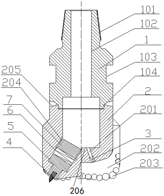
[0032] Embodiment 1, with reference to attached figure 1 , a bottom hole stress-induced unloading drill bit mentioned in the present invention includes a drill bit body 2, a support block 7, a spring 6, a stress unloading tooth matrix 5 and a stress unloading tooth 4, the support block 7, the spring 6, The stress unloading tooth parent body 5 is all installed in the special installation hole 204 of the shoulder of the drill bit body 2, and the stress unloading tooth 4 is installed on the stress unloading tooth parent body 5 and is located outside the drill bit body 2; the spring 6 is installed on the side of the stress unloading tooth body 5 close to the inside of the drill body, and is located between the support block 7 and the stress unloading tooth body 5; the combination of the stress unloading tooth body 5 and the stress unloading tooth 4 can be relatively Sliding in the direction of the spring axis; the special mounting hole 204 is located at the shoulder of the drill b...


PUM


Abstract

The invention relates to a shaft bottom stress-induced unloading drill bit and a method for increasing the drilling speed. According to the technical scheme, a supporting block, a spring and a stressunloading gear matrix are mounted in a special mounting hole of the shoulder of a drill bit body; a stress unloading gear is mounted on the stress unloading gear matrix; the spring is mounted on one side, close to the inside of the drill bit body, of the stress unloading gear matrix; a combination body of the stress unloading gear matrix and the stress unloading gear can slide relative to the axisdirection of the spring; drill bit cutting teeth are arranged on the outer side of a drill bit blade of the drill bit body; and the extending length of the stress unloading gear is larger than the extending length of the drill bit cutting teeth. The drill bit has the beneficial effects as follows: the stress unloading gear crushes the shaft bottom ahead of the drill bit cutting teeth at the bottom end of the crown of the drill bit body to form the circular groove shaft bottom, the shaft bottom stress is released, then the drill bit cutting teeth at the bottom end of the crown of the drill bitbody break rock under pressure and torque, and the drilling speed is increased in the whole rock breaking process through stress releasing and then overall rock breaking at the shaft bottom.

Description

technical field [0001] The invention relates to the field of petroleum drilling engineering, in particular to a stress-induced unloading drill bit at the bottom of a well and a method for increasing the drilling speed thereof. Background technique [0002] There are three main ways to improve the rock-breaking efficiency of drilling: increasing the rock-breaking energy of bottom-hole rock-breaking tools, optimizing the bottom-hole rock-breaking energy, and releasing the stress of bottom-hole rock. During the process, due to the serious attenuation of rock-breaking energy at the bottom of the well, it cannot be applied well. The method of releasing the rock stress at the bottom of the well to increase the drilling speed is represented by the ultra-high pressure jet-assisted rock-breaking and speed-up technology, but so far, The tool structure required by this type of technology is complicated, the installation is cumbersome, and the drilling efficiency is not high. So far, on...

Claims


Application Information

Patent Timeline
Patent Type & Authority Applications(China)
IPC IPC(8): E21B10/36E21B10/38E21B17/04
CPCE21B10/36E21B10/38E21B17/04
Inventor 马广军刘永旺路保平王志远柯珂张洪宁玄令超王恒
Owner CHINA PETROLEUM & CHEM CORP
Why Eureka
Try Eureka