
Wind generating set inhaul cable type steel cylinder tower and steel cylinder replacing method

A technology for a wind turbine generator set and a replacement method is applied in the directions of wind energy generation, installation/support of wind turbine configuration, engine components, etc. Power generation revenue time, improvement of mechanical performance, saving effect of demolition

Pending Publication Date: 2020-09-01
INNER MONGOLIA OF GIMHAE NEW ENERGY TECH +1
View PDF2 Cites 3 Cited by
  • Summary
  • Abstract
  • Description
  • Claims
  • Application Information

AI Technical Summary

Problems solved by technology

In order to maximize the benefits of wind farms, the second type of technical transformation requirements are more required by the market and policies, but the cost of the existing corresponding technical transformation methods is too high, which not only includes demolition of the original wind turbine foundation, tower, and construction of new wind farms. The foundation, re-provision of new towers, and the opportunity cost of power generation generated during the demolition, reconstruction, and new construction make it difficult for wind power technology to be promoted on a large scale, resulting in a serious waste of wind resources

Method used


Image

  • Wind generating set inhaul cable type steel cylinder tower and steel cylinder replacing method
  • Wind generating set inhaul cable type steel cylinder tower and steel cylinder replacing method
  • Wind generating set inhaul cable type steel cylinder tower and steel cylinder replacing method

Examples


Embodiment Construction

[0045] The following description illustrates specific embodiments of the invention sufficiently to enable those skilled in the art to practice and reproduce it.

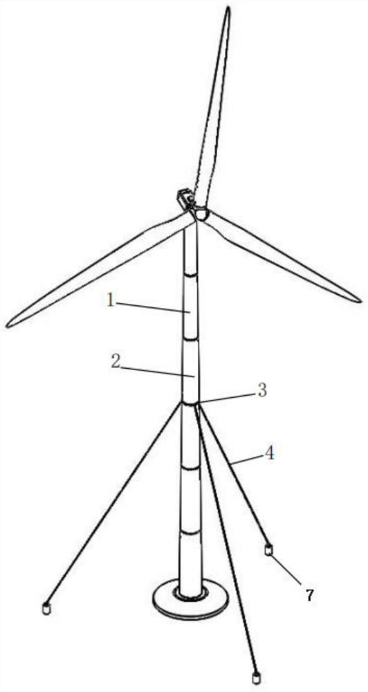
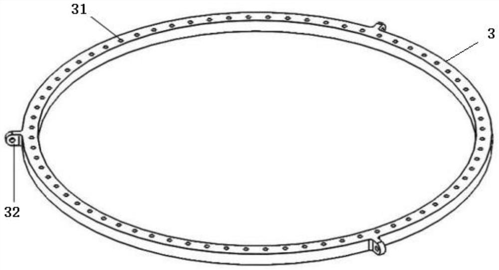
[0046] Such as figure 1 As shown, it is a structural schematic diagram of the cable-type steel cylinder tower of the wind power generating set in the present invention. Such as figure 2 Shown is a schematic structural view of the cable flange 3 in the present invention.

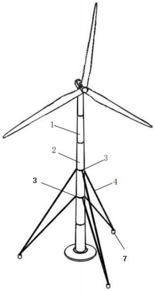
[0047] The cable-type steel tube tower of the wind power generating set includes: a tower tube section 1, a tower tube transition section 2, a cable flange 3, and a cable 4; the tower tube transition section 2 is provided with a tower tube transition section flange 21 at both ends, The flange 21 of the transition section of the tower is provided with flange bolt holes; the cable flange 3 is annular in shape, and is provided with a plurality of cable flange bolt holes 31 arranged in a circle, and a plurality of cable flange ears are arranged on th...


PUM


Abstract

The invention discloses a wind generating set inhaul cable type steel cylinder tower. The wind generating set inhaul cable type steel cylinder tower comprises a tower cylinder section, and is characterized by further comprising tower cylinder transition sections, an inhaul cable flange and an inhaul cable; tower cylinder transition section flanges are arranged at the two ends of each tower cylinder transition section, and flange bolt holes are formed in the tower cylinder transition section flanges; the inhaul cable flange is provided with an inhaul cable flange bolt hole, and the outer wall of the inhaul cable flange is provided with an inhaul cable flange lug plate; the inhaul cable flange is located between the two tower cylinder transition sections, and a flange connecting bolt penetrates through the flange bolt hole and the inhaul cable flange bolt hole to connect the two tower cylinder transition sections and the inhaul cable flange together; and the tower cylinder section is connected with the outer side ends of the two tower cylinder transition sections, one end of the inhaul cable is connected with the inhaul cable flange lug plate, and the other end of the inhaul cable isconnected with a ground anchoring point. The invention further discloses a steel cylinder replacing method of the wind generating set inhaul cable type steel cylinder tower. According to the wind generating set inhaul cable type steel cylinder tower and the steel cylinder replacing method, the stress path of the steel cylinder tower can be reasonably distributed, and the stress performance of thetower and joints is improved.

Description

technical field [0001] The invention relates to a tower frame of a wind power generating set, in particular to a cable-type steel cylinder tower frame of a wind power generating set and a method for replacing the steel cylinder. Background technique [0002] With the development of the wind power industry, large-scale wind turbines and elevated hubs have become the research and development direction of wind power support structures, based on the mature steel tower and flange industry chain, and at the same time subject to the domestic road transportation system's restrictions on large tower diameters At present, the steel tower support structure that meets the above research and development direction is mainly a flexible tower route, because the diameter cannot be increased without limit according to the increase of external load, so the resistance of the tower itself can only be improved by increasing the wall thickness Bending moment capacity, low material utilization effi...

Claims


Application Information

Patent Timeline
IPC IPC(8): F03D13/20E04H12/20
CPCF03D13/20E04H12/20Y02E10/72Y02E10/728F05B2240/917
Inventor 张明熠杨州汤丰艺张冬黄张裕张东灿施辉沈卫明
Owner INNER MONGOLIA OF GIMHAE NEW ENERGY TECH
Learn More