Blade and fan blade applying same

A blade and leeward technology, which is applied in the field of ventilation equipment, can solve the problems of screw wing vibration, lower production efficiency, uneven thickness of welds, etc., and achieve the effects of reducing vibration amplitude, improving rigidity, and riveting stability

Active Publication Date: 2020-09-01
叶剑明
View PDF14 Cites 1 Cited by
  • Summary
  • Abstract
  • Description
  • Claims
  • Application Information

AI Technical Summary

Problems solved by technology

[0002] The existing axial flow fan blades used in industry include a hub and multiple split blades. The blades are connected to the outer periphery of the hub by welding. However, due to the uneven thickness of the welds, in order to make the blades rotate smoothly, the The leaves need to be polished before and after painting to improve the dynamic balance performance, but this method will greatly reduce the production efficiency. In order to solve the above problems, such as figure 1 and figure 2 As shown, there is a fan blade formed by stacking two blades up and down in the existing market. The blade is made by stamping, which includes a hub and a spiral wing. The stacked blades are connected by riveting the hubs of the two.
[0003] Since the windward side of the blade will be affected by the positive pressure when it rotates, the blade will lean back. At the same time, no matter whether the side area of ​​the windward side on the front side of the hub is larger or smaller than its side area on the rear side of the hub, torque will be generated during rotation. The generated torsion will act on the side edges of the helix wing, causing the helix wing to vibrate back and forth, while the hub in the prior art sets riveting holes at the centerline position of the corresponding helix wing. The position is not fastened, its rigidity is particularly poor, and it is easy to vibrate under the influence of torsion, so it is necessary to develop a new type of blade

Method used


Image

  • Blade and fan blade applying same
  • Blade and fan blade applying same
  • Blade and fan blade applying same

Examples


Embodiment 1

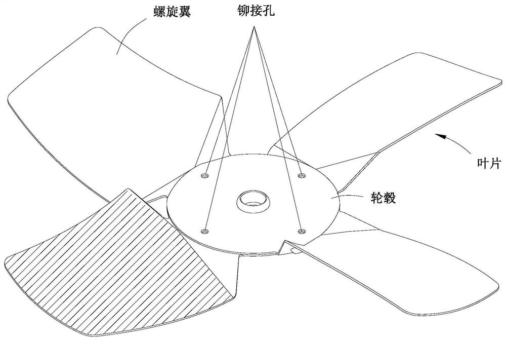
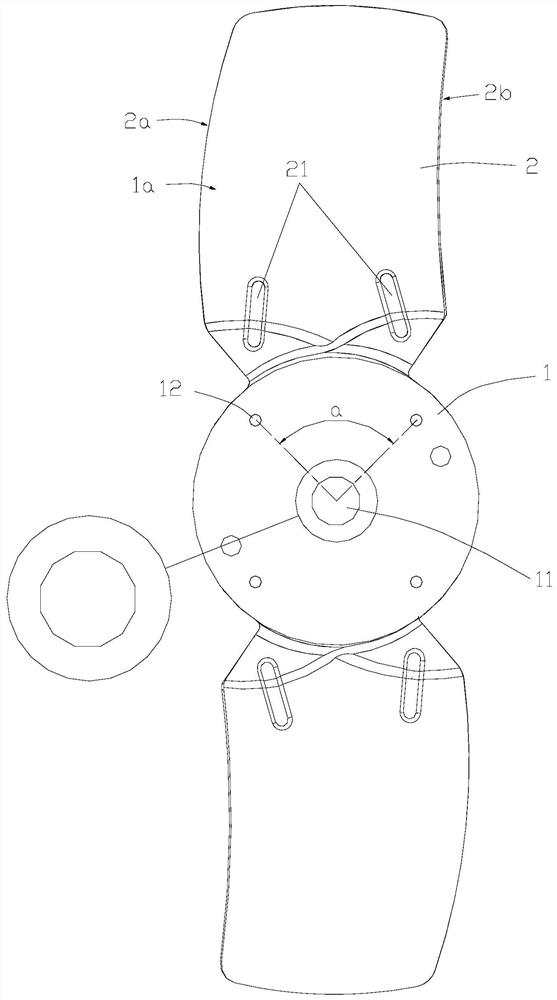
[0031] see Figure 3 to Figure 8 , the present embodiment provides a blade applied on the fan blade, which includes a hub 1 and at least two helical wings 2 arranged on the outer periphery of the hub 1, a shaft hole 11 is provided in the middle of the hub 1, and the root of the helical wing 2 is connected to the hub. 1 connection, the hub 1 is provided with riveting holes 12 at least at the edge positions on both sides close to the root of each spiral wing 2, and the riveting holes 12 are used for passing through the rivets 3 to rivet the blades stacked on the upper and lower layers. 11 is used for inserting for axle sleeve 4. Preferably, the hub 1 and the helical wing 2 are integrally formed by stamping. This processing method has a simple process flow and is conducive to manufacturing. The integrally formed blade has good rigidity, and the blade rotates stably with little vibration.

[0032] One side of the blade is the windward side 1a, and the other side is the leeward si...

Embodiment 2

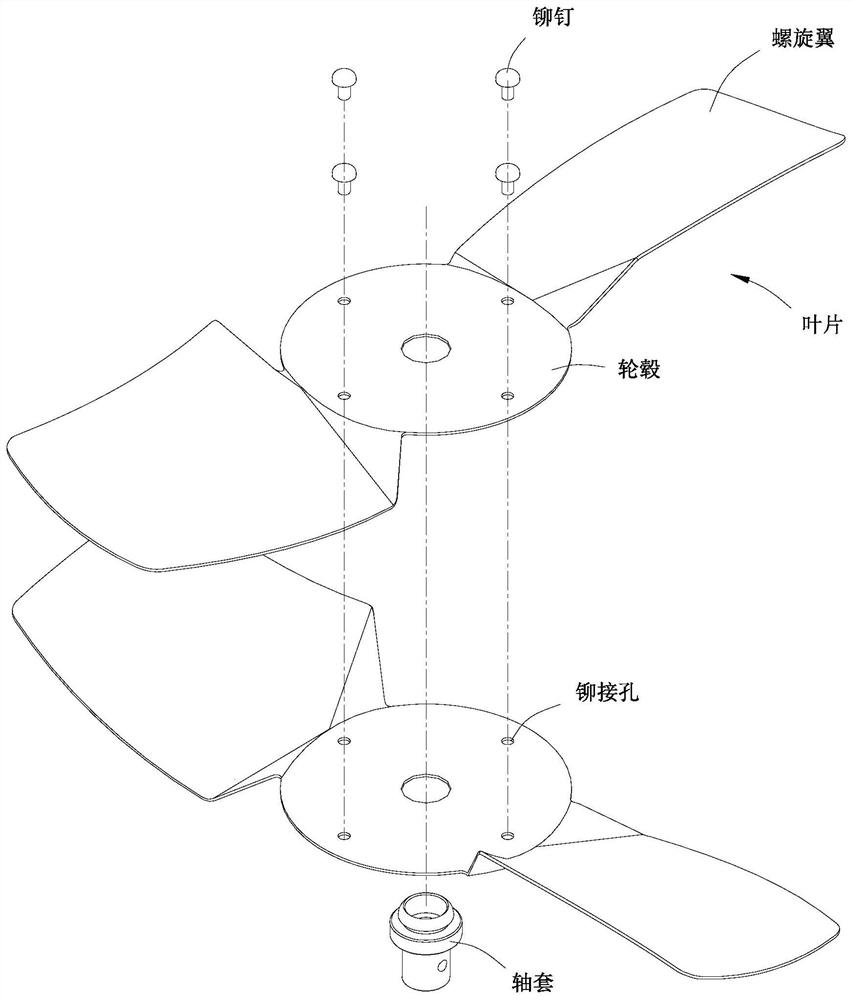
[0039] see Image 6 and Figure 8 , this embodiment provides a fan blade using the blade of Embodiment 1, which includes a bushing 4, a rivet 3 and two blades (101, 102) of Embodiment 1, and each blade (101, 102) is provided with two oppositely arranged A piece of spiral wing 2, two blades (101, 102) are stacked up and down at an angle of 90°, and include a first blade 101 on the upper layer, and a second blade 102 on the lower side, so that the two blades (101, 102) The riveting holes 12 are aligned, and the shaft holes 11 of the two blades (101, 102) are aligned, the rivet 3 penetrates the riveting holes 12 and the hub 1 of the riveting blades (101, 102), the upper end of the shaft sleeve 4 penetrates into the shaft hole 11 and is in the shaft hole Under the extrusion of the side of 11, plastic deformation occurs so as to be closely connected with the side of the shaft hole 11, and the two blades (101, 102) are riveted, thereby further preventing relative rotation between t...


PUM


Abstract

The invention belongs to the technical field of ventilation equipment, and particularly relates to a blade and a fan blade applying the same. The blade comprises a hub and at least two spiral wings arranged on the periphery of the hub. A shaft hole is formed in the middle of the hub, the root parts of the spiral wings are connected with the hub, and at least riveting holes are formed in the portions, close to the edges of the two sides of the root part of each spiral wing, of the hub. Compared with the prior art, the blade has the advantages that the positions of the riveting holes in the hubare reset, the riveting holes are formed in the portions, corresponding to the edges of the two sides of each spiral wing, of the hub, so that the rigidity of the spiral wings and the hub is improved,the riveting of the fan blade applying the blade is more stable, the spiral wings can effectively avoid the influence caused by positive pressure and torsion, the vibration amplitude of the spiral wings is reduced, and the wind noise is reduced.

Description

technical field [0001] The invention belongs to the technical field of ventilation equipment, in particular to blades and fan blades using the same. Background technique [0002] The existing axial flow fan blades used in industry include a hub and multiple split blades. The blades are connected to the outer periphery of the hub by welding. However, due to the uneven thickness of the welds, in order to make the blades rotate smoothly, the The leaves need to be polished before and after painting to improve the dynamic balance performance, but this method will greatly reduce the production efficiency. In order to solve the above problems, such as figure 1 and figure 2 As shown, there is a fan blade formed by stacking two blades up and down in the existing market. The blade is made by stamping, which includes a hub and a spiral wing. The stacked blades are connected by riveting the hubs of the two blades. [0003] Since the windward side of the blade will be affected by the ...

Claims


Application Information

Patent Timeline
Patent Type & Authority Applications(China)
IPC IPC(8): F04D29/32F04D29/34
CPCF04D29/325F04D29/329F04D29/34
Inventor 杨志舜
Owner 叶剑明
Why Eureka
Try Eureka