Flow-adjusting control valve and electricity generation assembly

A control valve and flow regulation technology, applied in the directions of hydroelectric power generation, engine components, valve details, etc., can solve the problem of easy wear and tear of hydroelectric generators, and achieve the effect of avoiding excessively fast water flow and balanced water flow.

Pending Publication Date: 2020-09-01
GUANGDONG YONGQUAN VALVE TECH
View PDF0 Cites 0 Cited by
  • Summary
  • Abstract
  • Description
  • Claims
  • Application Information

AI Technical Summary

Problems solved by technology

Excessive speed of the hydroelectric generator will

Method used


Image

  • Flow-adjusting control valve and electricity generation assembly
  • Flow-adjusting control valve and electricity generation assembly
  • Flow-adjusting control valve and electricity generation assembly

Examples


Embodiment Construction

[0025] Below, the present invention will be further described in conjunction with the accompanying drawings and specific implementation methods. It should be noted that, under the premise of not conflicting, the various embodiments described below or the technical features can be combined arbitrarily to form new embodiments. .

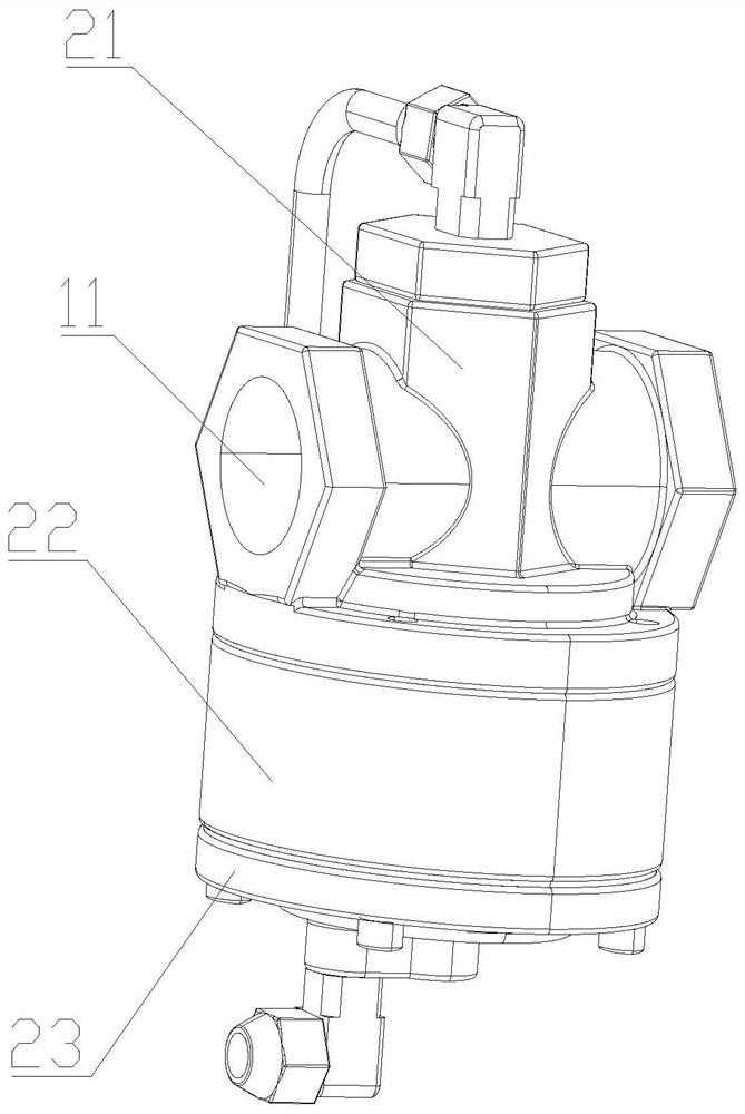
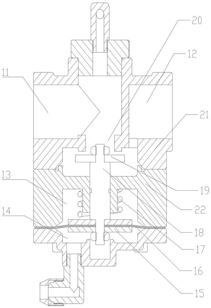
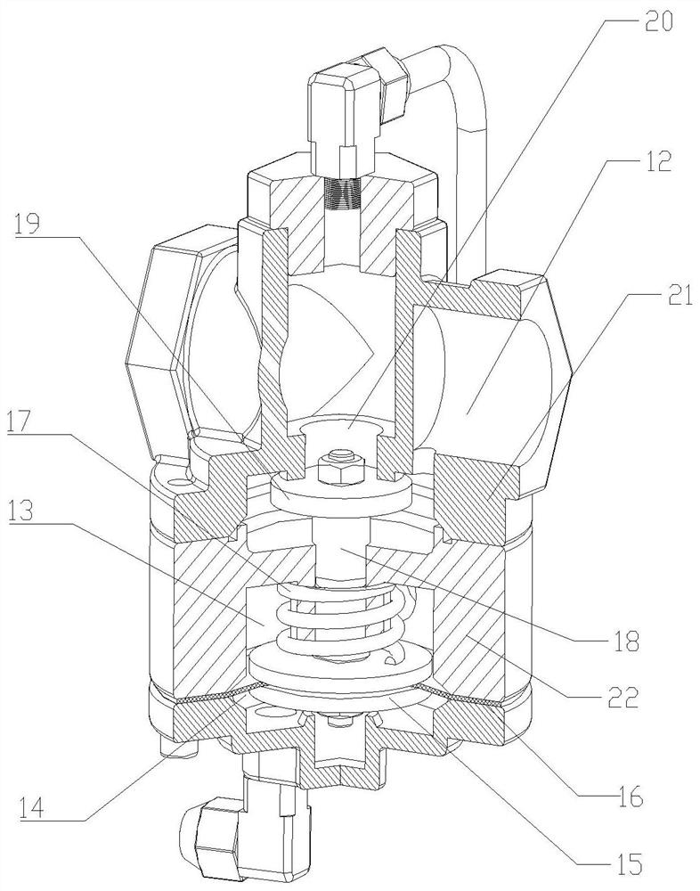
[0026] Such as Figure 1-3 The flow regulating control valve shown includes a valve body, and the valve body is provided with an inlet 11, an outlet 12, and an accommodation chamber communicated with the outlet 12. opening 20;

[0027] The valve body is also provided with a lower pressure chamber 14 and a flow regulation assembly, the flow regulation assembly is slidingly connected with the valve body, the lower pressure chamber 14 is arranged below the receiving chamber, the lower pressure chamber 14 communicates with the inlet 11 through a pipeline, and the upper end of the flow regulation assembly is placed In the accommodation chamber, the lower ...


PUM


Abstract

The invention discloses a flow-adjusting control valve and an electricity generation assembly. The flow-adjusting control valve comprises a valve body, an inlet, an outlet and an accommodating cavitycommunicating with the outlet are formed in the valve body, the accommodating cavity is formed in the lower part of the inlet, and an opening communicating with the inlet is formed in the accommodating cavity; and a lower pressure cavity and a flow-adjusting assembly are further arranged in the valve body, the flow-adjusting assembly is slidably connected with the valve body, the lower pressure cavity is formed in the lower part of the accommodating cavity, the lower pressure cavity communicates with the inlet through a pipeline, the upper end of the flow-adjusting assembly is arranged in theaccommodating cavity, and the upper end of the flow-adjusting assembly corresponds to the opening to form a sealing piece. The flow-adjusting control valve can control the flow rate of water flowing into a hydroelectric generator in real time, and the hydroelectric generator is prevented from being damaged due to the excessive flow rate in the hydroelectric generator.

Description

technical field [0001] The invention relates to the technical field of valves, in particular to a flow regulating control valve. Background technique [0002] The urban smart pipe network control system often monitors and controls the pressure and flow of the pipe network through various electronic components, such as electromagnetic flowmeters, electronic pressure gauges, wireless wires, sensors, electric actuators and control electrical boxes. In remote suburbs, there is often no municipal power supply, and solar power is generally used to power the electronic components in the pipeline. However, there are various shortcomings in solar power generation equipment, such as insufficient power generation in cloudy days; the equipment needs to be installed in the open air, and the installation space is large; the storage battery 7 of the power generation equipment is often destroyed or stolen. [0003] The storage electromagnetic has a certain service life. During the long-ter...

Claims


Application Information

Patent Timeline
IPC IPC(8): F16K17/30F16K17/34F16K27/02F16K31/126F03B11/00F03B13/00F03B15/06
CPCF03B11/004F03B13/00F03B15/06F16K17/30F16K17/34F16K27/02F16K31/1262Y02E10/20
Inventor 陈炯亮霍达文区展剑
Owner GUANGDONG YONGQUAN VALVE TECH
Why Eureka
Try Eureka