Pulse solenoid valve

A solenoid valve, pulse type technology, applied in the direction of valve lift, valve details, valve device, etc., can solve the problem of continuous power supply of the valve, and achieve the effect of good heat dissipation, simple and compact structure, and easy manufacture

Pending Publication Date: 2020-09-01
BEIFANG UNIV OF NATITIES
View PDF0 Cites 0 Cited by
  • Summary
  • Abstract
  • Description
  • Claims
  • Application Information

AI Technical Summary

Problems solved by technology

[0006] The first aspect of the present invention is to solve the problem that the existing valves need to be continuously energized during the working process, and provides a pulse type electromagnetic valve, including a valve body, an electromagnetic mechanism and an angle control mechanism. The valve body is provided with an inlet and an outlet. The inlet and the outlet are connected through an internal flow channel arranged in the valve body, and a valve core is arranged in the internal flow channel, and the valve core is connected with the angle control mechanism through a valve stem, and the electromagnetic mechanism is connected with the angle control mechanism connected, among them,

Method used


Image

  • Pulse solenoid valve
  • Pulse solenoid valve
  • Pulse solenoid valve

Examples


Embodiment 1

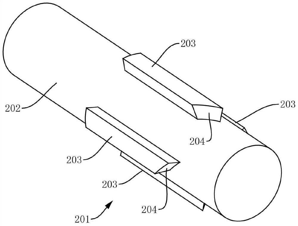
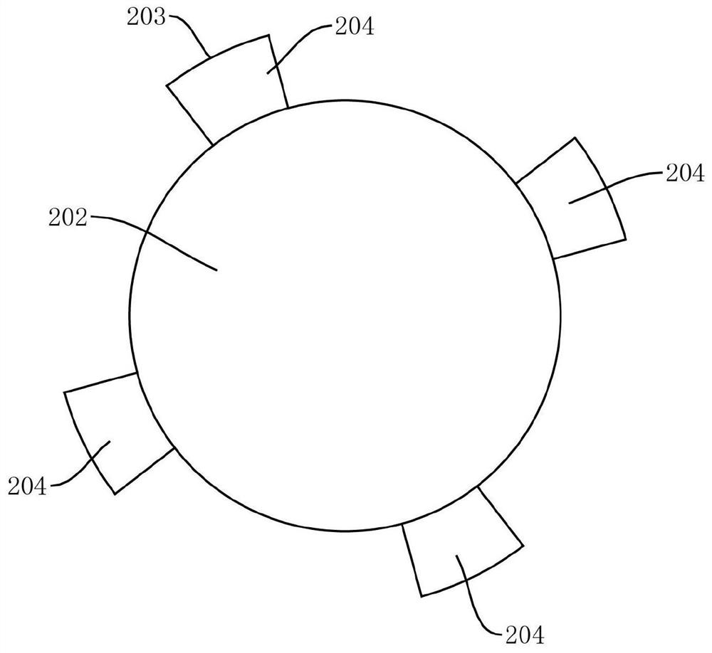
[0055] see Figure 1-Figure 10 In this embodiment, a pulse solenoid valve is provided, including a valve body 300, an electromagnetic mechanism, and an angle control mechanism 200. The valve body 300 is provided with an inlet 301 and an outlet 302, and the inlet 301 and the outlet 302 are arranged on the valve The internal channel 303 in the body 300 is connected, and the internal channel 303 is provided with a valve core 304, the valve core 304 is connected with the angle control mechanism 200 through the valve stem 305, and the electromagnetic mechanism is connected with the angle The control mechanism 200 is connected, wherein,

[0056] The electromagnetic mechanism is used to generate a magnetic force when receiving a pulse electric signal, and drive the angle control mechanism 200 to act through the magnetic force (one pulse electric signal acts once),

[0057] The angle control mechanism 200 is used to drive the valve stem 305 to rotate at a set angle under the drive of...

Embodiment 2

[0083] The main difference between this embodiment 2 and the above-mentioned embodiment 1 is that, in the pulse solenoid valve provided by this embodiment, a transmission mechanism is also provided between the valve stem 305 and the angle control mechanism 200, and the transmission mechanism One end of one end is connected with the valve rod 305, and the sliding sleeve 215 is arranged at the other end of the transmission mechanism, and the transmission ratio of the transmission mechanism can be greater than 1 or equal to 1.

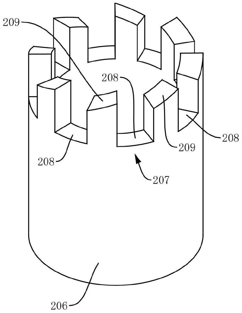
[0084] In principle, the more the number of constraining parts 207 arranged in the limit sleeve 206 along the circumferential direction, the smaller the rotation angle of the spool 304 under the action of a single pulse electric signal, and the higher the precision. However, in practice, due to processing Due to the accuracy and the dimensional parameters of the spacer sleeve 206, the number of the constraining parts 207 cannot be too large. For this reaso...

Embodiment 3

[0088] Since in the existing solenoid valve, whether the electromagnet and the armature 104 act (or engage) cannot be judged from the outside of the housing 101, so in the solenoid valve provided in this embodiment, the pushing part 210 (such as extending Rod 214) is also provided with state detection contact 601, as Figure 10 As shown, it can be preferentially arranged on the side of the extension rod 214. The housing 101 is provided with a fixed contact 602. 603 connected, the detection terminal 603 can be used to connect controllers, such as single-chip microcomputers, PLCs, etc.; 601 is in contact with the fixed contact 602. At this time, the state detection circuit is connected, and the controller can receive the corresponding signal through the detection terminal 603, indicating that the electromagnet and the armature 104 in the solenoid valve have been activated, so that the internal Whether or not the electromagnet and the armature 104 act (or engage) cannot be judge...


PUM


Abstract

The invention relates to a pulse solenoid valve which comprises a valve body, an electromagnetic mechanism and an angle control mechanism. The valve body is provided with an inlet and an outlet. The inlet and the outlet communicate with each other through an internal passageway in the valve body. A valve element is arranged in the internal passageway and is connected with the angle control mechanism through a valve rod. The electromagnetic mechanism is connected with the angle control mechanism. The electromagnetic mechanism is used for driving the angle control mechanism to act when receivingpulse electric signals. The angle control mechanism is used for driving the valve rod to rotate by a set angle under the driving of the electromagnetic mechanism and locking the valve rod to limit the valve rod to rotate when the electromagnetic mechanism is powered off. The valve element is used for rotating to adjust the opening degree of the valve body under the driving of the valve rod. The pulse solenoid valve is simple and compact in structure and convenient to manufacture, can change and maintain the state of the valve rod instantly after instantaneously emitting the pulse electric signals without being powered on continuously, and is beneficial for cooling when saving electric energy, thereby effectively avoiding the heat problem and other problems caused by continuous power-on.

Description

technical field [0001] The invention relates to the technical field of valves, in particular to a pulse electromagnetic valve. Background technique [0002] Solenoid valve is an automatic basic component that uses electromagnetics to control fluids. It is a common actuator and is mainly used to adjust the direction, flow, speed and other parameters of media in industrial control systems. The solenoid valve can cooperate with different circuits to achieve the expected control, and the control accuracy and flexibility can be guaranteed. Solenoid valves can be divided into many types according to their structure and specific functions. The most commonly used ones are check valves, safety valves, directional control valves, speed regulating valves, etc. Different solenoid valves play a role in different positions of the control system. [0003] In the current conventional technical solutions, the on-off of the circuit is usually used to control the presence or absence of the ma...

Claims


Application Information

Patent Timeline
Patent Type & Authority Applications(China)
IPC IPC(8): F16K31/06F16K1/22F16K1/50
CPCF16K1/221F16K1/50F16K31/0655F16K31/0675
Inventor 张白毛建东
Owner BEIFANG UNIV OF NATITIES
Why Eureka
Try Eureka