Optical module adjustment test method and device

A test method and technology of optical modules, which are applied in the testing of optical instruments, measuring devices, and testing of machinery/structural components, etc., can solve problems such as soaring costs, low product yield, and difficulty in eliminating

Pending Publication Date: 2020-09-01
弗提图德萨沃有限公司
View PDF0 Cites 4 Cited by
  • Summary
  • Abstract
  • Description
  • Claims
  • Application Information

AI Technical Summary

Problems solved by technology

[0004] The main factors that usually lead to the adjustment deviation of optical modules are the structural tolerances of parts and the assembly tolerances of the assembly process, and these two errors are not easy to eliminate; in addition, for optical components such as lenses, it is inevitable Due to the existence of aberrations, the existing assembly and testing based on mechanical alignment cannot overcome the influence of aberration factors on the final imaging effect
Therefore, the existing optical component assembly and testing process and technology often lead to low product yield, low efficiency, poor product stability and consistency, and soaring costs. The current method is not suitable for mass production

Method used


Image

  • Optical module adjustment test method and device
  • Optical module adjustment test method and device
  • Optical module adjustment test method and device

Examples


Embodiment Construction

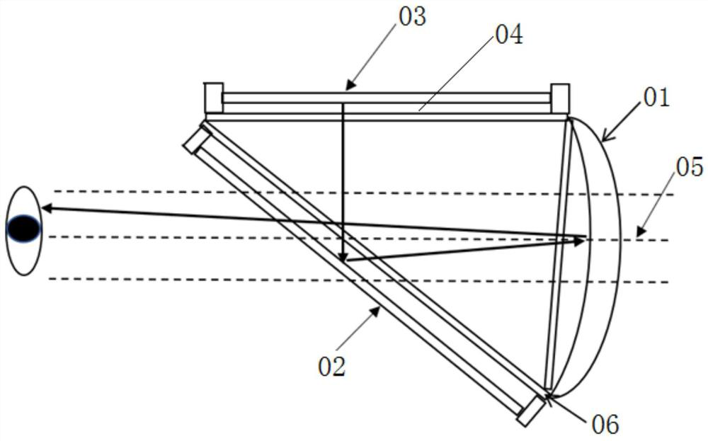
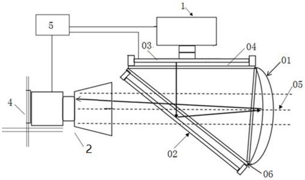
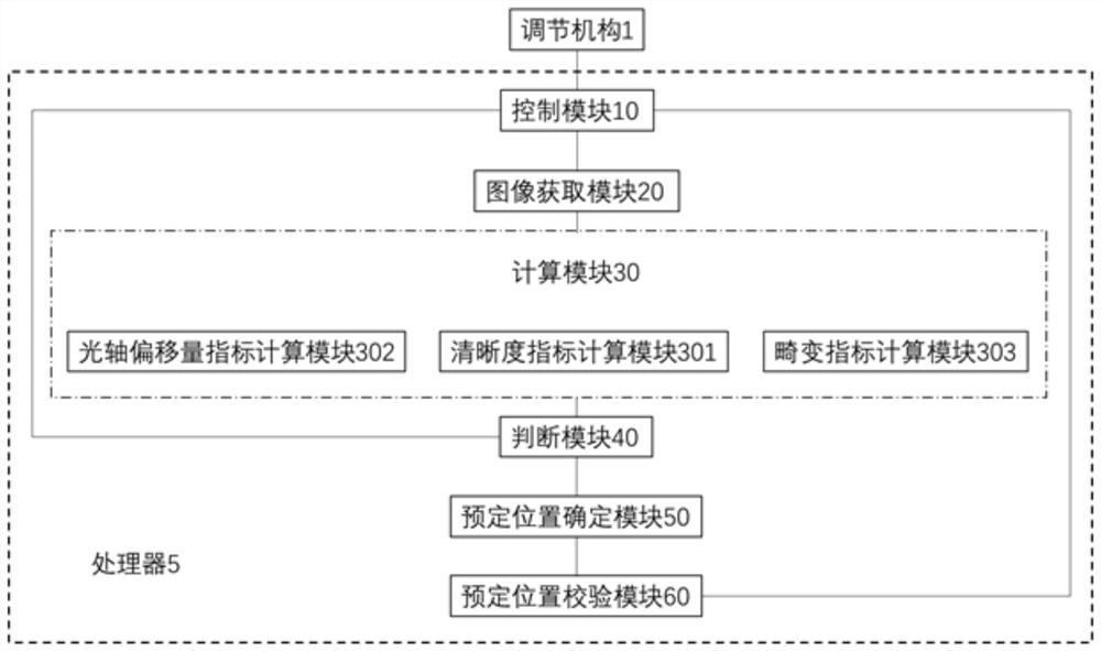
[0101] Aiming at the problem that the existing assembly and testing based on mechanical alignment cannot overcome the influence of aberration factors on the final imaging effect, the present invention provides a method and device for adjusting and testing optical modules. The display device is installed at a predetermined position relative to the main body of the optical module. The display device receives and displays the signal of the test legend, which is imaged in the human eye through the optical path transmission of the optical module. The installation accuracy of the display device affects the human eye. Imaging quality, the device sets a camera on the imaging optical path of the optical module to simulate the visual effect of the human eye, collects the imaging of the test pattern displayed by the display device in the camera, and judges the display through the image quality index of the collected test pattern Whether the installation position of the device is the prede...


PUM


Abstract

The invention provides an optical module adjustment test method and device. According to the device, a camera is arranged on an imaging light path of an optical module, so the visual effect of human eyes is simulated; the method comprises acquiring an image of a test legend displayed by a display device in a camera, judging whether the display device reaches a preset position or not according to adefinition index, an optical axis offset index and a distortion index of the acquired test legend image, and adjusting the position of the display device on line until the design requirement of a quality index of the test legend image is met. According to the device, the position of the display device can be adjusted in time according to the quality index of the test legend image shot by the camera, adverse effects of the structural tolerance, the assembly tolerance and the aberration of the optical module on the imaging quality of the optical module are compensated to a certain extent, and the product yield and the assembly efficiency are improved.

Description

technical field [0001] The invention relates to an optical module assembly testing technology, in particular to an optical module assembly testing method and device. Background technique [0002] Modern computer technology, display technology, sensor technology and other scientific technologies have promoted the development of AR (Augmented Reality, referred to as Augmented Reality) and VR (Virtual Reality, referred to as Virtual Reality) experience systems. VR scenes create a multi-dimensional information space. The virtual information environment enables users to have an immersive sense of immersion and has a perfect interaction ability with the environment; the AR scene applies virtual information to the real world, and the real environment and the virtual environment are superimposed on the same screen or space in real time simultaneously exist. [0003] The principle of AR and VR display devices is to pull the close-up images generated by the display to the distance th...

Claims


Application Information

Patent Timeline
Patent Type & Authority Applications(China)
IPC IPC(8): G01M11/00
CPCG01M11/00
Inventor 不公告发明人
Owner 弗提图德萨沃有限公司
Why Eureka
Try Eureka