Automatic preparation and strength testing device for concrete test block for building construction

A concrete test block and strength testing technology, which is applied in the direction of measuring device, using repeated force/pulsation force to test material strength, and preparation of test samples, can solve the problem of inability to perform strength test, increase construction trouble, and prolong construction cycle and other issues to achieve flexibility, reduce heat loss, and save energy

Inactive Publication Date: 2020-09-01
张延东
View PDF0 Cites 3 Cited by
  • Summary
  • Abstract
  • Description
  • Claims
  • Application Information

AI Technical Summary

Problems solved by technology

The compressive strength of concrete test block is a key index reflecting the construction quality of an engineering concrete. It is very important whether the method and procedure of test block making are appropriate. At present, in the field of building construction, especially the wall of reinforced concrete structure, the strength of concrete has a certain impact. Certain requirements require strength testing of the poured concrete for the building, but the existing method is to take out a par...

Method used


Image

  • Automatic preparation and strength testing device for concrete test block for building construction
  • Automatic preparation and strength testing device for concrete test block for building construction

Examples


Embodiment 1

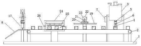
[0024] see Figure 1-2 According to an embodiment of the present invention, a concrete test block automatic preparation and strength testing device for building construction includes a bottom plate 1, a conveyor belt 2 is provided above the bottom plate 1, and a mixing box body 3 is provided at one end of the conveyor belt 2, The bottom of the mixing tank body 3 is provided with a discharge device, the discharge device includes a discharge pipe 4, the discharge pipe 4 is provided with an electromagnetic control valve 5, and one side of the electromagnetic control valve 5 is provided with A flow meter 6, one end of the discharge pipe 4 is fixedly provided with a first infrared sensor, the electromagnetic control valve 5, the flow meter 6 and the first infrared sensor are all electrically connected to the controller 7, and the stirring tank One side of the main body 3, and a beating and oscillating device is provided above the conveyor belt 2, and a drying device is provided on ...

Embodiment 2

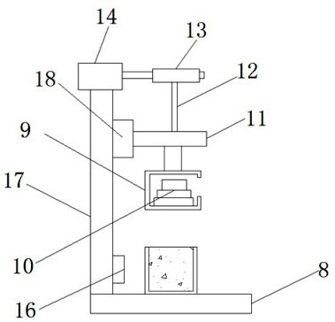
[0026] see Figure 1-2, for the sliding device, the sliding device includes a slide rail 17, the inside of the slide rail 17 is provided with a slider 18, one side of the slider 18 is fixedly connected to one end of the hanger 11, and the hanger One end of 11 is provided with a sliding device, which can increase the stability of the hanger 11 in the lifting process, and increase the stability of the striking head 9 when the concrete test block is hit; for the striking vibration device, the striking vibration The device comprises an impact plate 19, one side of the impact plate 19 is fixedly provided with a chute 20, the inside of the chute 20 is provided with an L-shaped bar 21, and the end of the L-shaped bar 21 away from the chute 20 is connected to the The turntable 22 is connected, the L-shaped rod 21 is connected to the eccentric part of the turntable 22 through a movable pin, one side of the turntable 22 is connected to the output end of the second motor 23, and the stri...


PUM


Abstract

The invention discloses an automatic preparation and strength testing device for a concrete test block for building construction. The device comprises a bottom plate; a conveying belt is arranged above the bottom plate; a stirring box body is arranged at one end of the conveying belt; a discharging device is arranged at the bottom of the stirring box body; the discharging device comprises a discharging pipe; an electromagnetic control valve is arranged on the discharging pipe; a flow meter is arranged on one side of the electromagnetic control valve; a first infrared sensor is fixedly arrangedat one end of the discharging pipe; the electromagnetic control valve, the flow meter and the first infrared sensor are all electrically connected with a controller; and a beating and vibrating device is arranged on one side of the stirring box body and located above the conveying belt. The device has the beneficial effects that the structure is simple, the concrete test block can be automatically prepared, the labor intensity of workers is greatly reduced, meanwhile, the strength of the prepared concrete test block can be tested, and the safety of building use is improved.

Description

technical field [0001] The invention relates to the field of building construction, in particular to a device for automatic preparation and strength testing of concrete test blocks for building construction. Background technique [0002] Cubic test blocks, also known as concrete test blocks, reflect the construction quality of concrete structures. The compressive strength of concrete test block is a key index reflecting the construction quality of an engineering concrete. It is very important whether the method and procedure of test block making are appropriate. At present, in the field of building construction, especially the wall of reinforced concrete structure, the strength of concrete has a certain impact. Certain requirements require strength testing of the poured concrete for the building, but the existing method is to take out a part of the poured concrete and place it in a mold for static molding. The static molding reduces work efficiency and prolongs the construct...

Claims


Application Information

Patent Timeline
IPC IPC(8): G01N3/34G01N3/02G01N1/44G01N1/36G01N1/28
CPCG01N1/28G01N1/36G01N1/44G01N3/02G01N3/34G01N2203/001G01N2203/0019
Inventor 张延东
Owner 张延东
Why Eureka
Try Eureka