Robot autonomous tracking method based on vision

An autonomous tracking and robot technology, applied in the direction of instruments, computer parts, image data processing, etc., can solve the problem of not using path planning, etc., and achieve the effect of long tracking distance and strong tracking ability

Pending Publication Date: 2020-09-01
ZHAOTONG POWER SUPPLYING BUREAU OF YUNNAN POWER GRID
View PDF10 Cites 4 Cited by
  • Summary
  • Abstract
  • Description
  • Claims
  • Application Information

AI Technical Summary

Problems solved by technology

The traditional methods mentioned above are more about the precise tracking of the target and tracking the target trajectory but without path planning, which means that the robot can only track nearby targets

Method used


Image

  • Robot autonomous tracking method based on vision
  • Robot autonomous tracking method based on vision
  • Robot autonomous tracking method based on vision

Examples


Embodiment 1

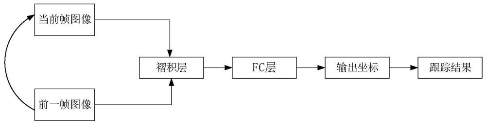
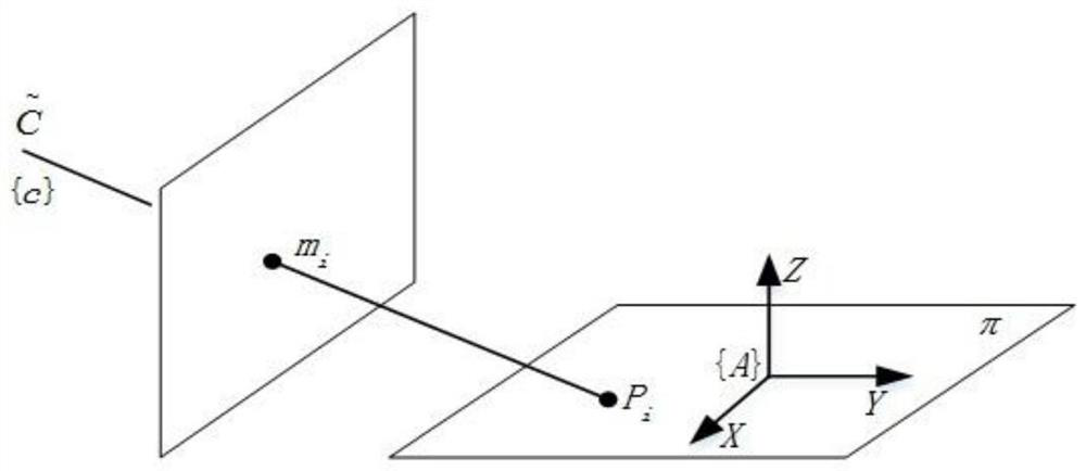
[0030] Embodiment 1: as Figure 1-7 As shown, a vision-based robot autonomous tracking method, firstly, manually select the tracking target, set the input of CNN as the target and the surrounding background area; then divide the environment into different categories according to the training data set; establish a very Coordinate local map, take the robot as the center of the polar coordinate system, establish the conversion relationship between the pixel coordinate point and the plane coordinate point and the grid coordinate, and calculate the grid pixel as the statistical grid obstacle; set the starting grid of the robot The grid coordinates, the robot target position is obtained through the target tracking algorithm, and finally the A* algorithm is used to complete the optimal path search. For this application, choose a tracking model similar to GOTURN, such as figure 1 As shown, the CNN model is used to extract the basic features of the current frame and the previous frame...


PUM


Abstract

The invention discloses a robot autonomous tracking method based on vision, and belongs to the technical field of automatic robots. According to the invention, the target position is determined and the surrounding environment planning path is perceived by using the scene segmentation model based on the GOTURN tracking model and the SegNet so as to avoid obstacles; the system establishes a mappingrelationship between pixel coordinates and two-dimensional plane coordinates through parallel projection, constructs a local grid map under polar coordinates by fusing visual positioning with an environmental mathematical model, and finally plans an optimal trajectory between a robot and a target through an A * algorithm. And relatively strong tracking capability and relatively long tracking distance can be realized in indoor and corridor environments.

Description

technical field [0001] The invention relates to a vision-based robot autonomous tracking method, which belongs to the technical field of automatic robots. Background technique [0002] In recent years' research, Sidenbladh et al. used skin color segmentation to detect target persons from RGB images and track their heads. The detection results are easily affected by factors such as ambient lighting and target motion, which affect system performance. Adiwahono et al. proposed a flexible leg feature detection method, but it is sensitive to changes in human pose. Gockley et al. used the standard particle filter algorithm to segment laser scanner data and track potential targets. The authors designed two tracking schemes, direction tracking and path tracking, but the system lacked identifiable visual information and its effective range was less than 3.5m. Wang et al. used the 3D reconstruction based on the binocular camera to obtain the relative position between the robot and th...

Claims


Application Information

Patent Timeline
Patent Type & Authority Applications(China)
IPC IPC(8): G06T7/246G06K9/62G06K9/34G06K9/00
CPCG06T7/246G06T2207/10024G06T2207/10016G06T2207/20081G06T2207/20084G06V20/10G06V10/267G06F18/2415
Inventor 范江波郑昆徐云水赵泽彪邱平李锐
Owner ZHAOTONG POWER SUPPLYING BUREAU OF YUNNAN POWER GRID
Why Eureka
Try Eureka