Silicon controlled rectifier adjusting circuit of high-voltage lamp strip

A technology for adjusting circuits and thyristors, applied in electrical components and other directions, can solve the problem of unable to achieve simultaneous color temperature, control brightness and color temperature, increase the width of the light strip, etc., to achieve a comfortable working mood, reduce installation difficulty, warm and warm body relaxing effect

Inactive Publication Date: 2020-09-01
GUANGDONG MICROVIEW TECH CO LTD
View PDF0 Cites 2 Cited by
  • Summary
  • Abstract
  • Description
  • Claims
  • Application Information

AI Technical Summary

Problems solved by technology

[0002] At present, the existing high-voltage light strips can generally support thyristor dimming, and thyristors are generally connected in series in the front cut or back cut, and can be connected to light strips such as two color circuits, but the dimming range is very narrow and cannot be realized. While dimming, the temperature can be adjusted at the same time; and the light strip with color temperature generally requires two color loops to mix colors to achieve color temperature adjustment, and the two loops are usually connected to a common positive or common negative, and at least three lines are required to achieve it. Three lines are applied to the light strip, which increases the cost and the width of the light strip, and cannot use silicon controlled rectifiers to control brightness and color temperature

Method used


Image

  • Silicon controlled rectifier adjusting circuit of high-voltage lamp strip
  • Silicon controlled rectifier adjusting circuit of high-voltage lamp strip
  • Silicon controlled rectifier adjusting circuit of high-voltage lamp strip

Examples


Embodiment Construction

[0017] In order to make the above objects, features and advantages of the present invention more comprehensible, specific implementations of the present invention will be described in detail below in conjunction with the accompanying drawings. In the following description, numerous specific details are set forth in order to provide a thorough understanding of the present invention. However, the present invention can be implemented in many other ways different from those described here, and those skilled in the art can make similar improvements without departing from the connotation of the present invention, so the present invention is not limited by the specific embodiments disclosed below.

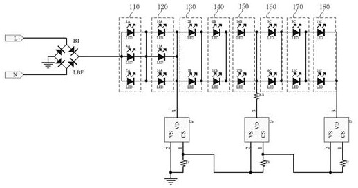
[0018] see figure 1 , the present invention provides a thyristor regulating circuit for high-voltage lamp strips. The high-voltage lamp strip thyristor regulating circuit includes: a live wire input terminal L, a neutral line input terminal N, a full-bridge rectifier module B1, and a firs...


PUM


Abstract

The invention discloses a silicon controlled rectifier adjusting circuit of a high-voltage lamp strip. The silicon controlled rectifier adjusting circuit comprises a live wire input end, a zero line input end, a full-bridge rectification module, a first group of LED circuit modules, a second group of LED circuit modules, a third group of LED circuit modules, a first silicon controlled rectifier chip, a second silicon controlled rectifier chip and a third silicon controlled rectifier chip. The lamp strip comprises a plurality of minimum lamp strip units, the minimum lamp strip units are arranged in parallel, and each minimum lamp strip unit comprises the silicon controlled rectifier adjusting circuit of the high-voltage lamp strip in any embodiment. According to the silicon controlled rectifier adjusting circuit of the high-voltage lamp strip, the defects of the application of an existing LED lamp strip are overcome, an external large-size power supply is removed, and the LED lamp stripis directly connected to the mains supply for use, so that the LED lamp strip is free of driving, the installation difficulty is reduced, and the silicon controlled rectifier adjusting circuit of thehigh-voltage lamp strip can be well applied to a narrow space and is not limited by the size and power adaptation of the power supply. The silicon controlled rectifier adjusting circuit of the high-voltage lamp strip is compatible with the existing silicon controlled rectifier dimming circuits, and saves the application cost.

Description

technical field [0001] The invention relates to the technical field of electronic circuits, in particular to a thyristor regulating circuit for a high-voltage lamp strip. Background technique [0002] At present, the existing high-voltage light strips can generally support thyristor dimming, and thyristors are generally connected in series in the front cut or back cut, and can be connected to light strips such as two color circuits, but the dimming range is very narrow and cannot be realized. While dimming, the temperature can be adjusted at the same time; and the light strip with color temperature generally requires two color loops to mix colors to achieve color temperature adjustment, and the two loops are usually connected to a common positive or common negative, and at least three lines are required to achieve it. Three wires are applied to the light strip, which increases the cost and the width of the light strip, and the thyristor cannot be used to control the brightne...

Claims


Application Information

Patent Timeline
Patent Type & Authority Applications(China)
IPC IPC(8): H05B45/30H05B45/20H05B45/10
CPCH05B45/10H05B45/20H05B45/30
Inventor 何志亮
Owner GUANGDONG MICROVIEW TECH CO LTD
Why Eureka
Try Eureka