Two-way guide-in vessel puncture device

A catheter and blood vessel technology, which is applied in the field of bidirectional introduction of blood vessel puncture devices to achieve the effects of reducing complications, reducing the number of punctures, and reducing patient damage

Pending Publication Date: 2020-09-04
刘阳 +1
View PDF12 Cites 1 Cited by
  • Summary
  • Abstract
  • Description
  • Claims
  • Application Information

AI Technical Summary

Problems solved by technology

[0002] At present, the catheter sheath for vascular puncture is introduced into the catheter sheath in one direction. Through the puncture technology, the catheter sheath is inserted into the catheter sheath to establish a unidirectional channel from the outside to the blood vessel cavity, and the puncture needle is punctured into the artery or vein, and the catheter is inserted into the proximal or distal end. Insert the guide wire, insert the vascular sheath along the guide wire, and establish a passage from the outside to the vascular cavity, but clinically, it is common for patients with lesions on both sides of the puncture point. If you need to solve the bilateral lesions, you need to do two or even multiple punctures Or cut the blood vessel to complete the two-way lesion treatment
Traditional introducer sheaths such as figure 1 As shown, the vascular catheter sheath can only be inserted in one direction, and the simultaneous treatment of lesions at the proximal end and distal end of the piercing point cannot be solved at the same time, or can be solved by using minimally invasive methods

Method used


Image

  • Two-way guide-in vessel puncture device
  • Two-way guide-in vessel puncture device
  • Two-way guide-in vessel puncture device

Examples


Embodiment Construction

[0024] The present invention will be described in further detail below in conjunction with the examples.

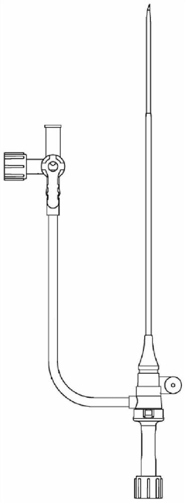
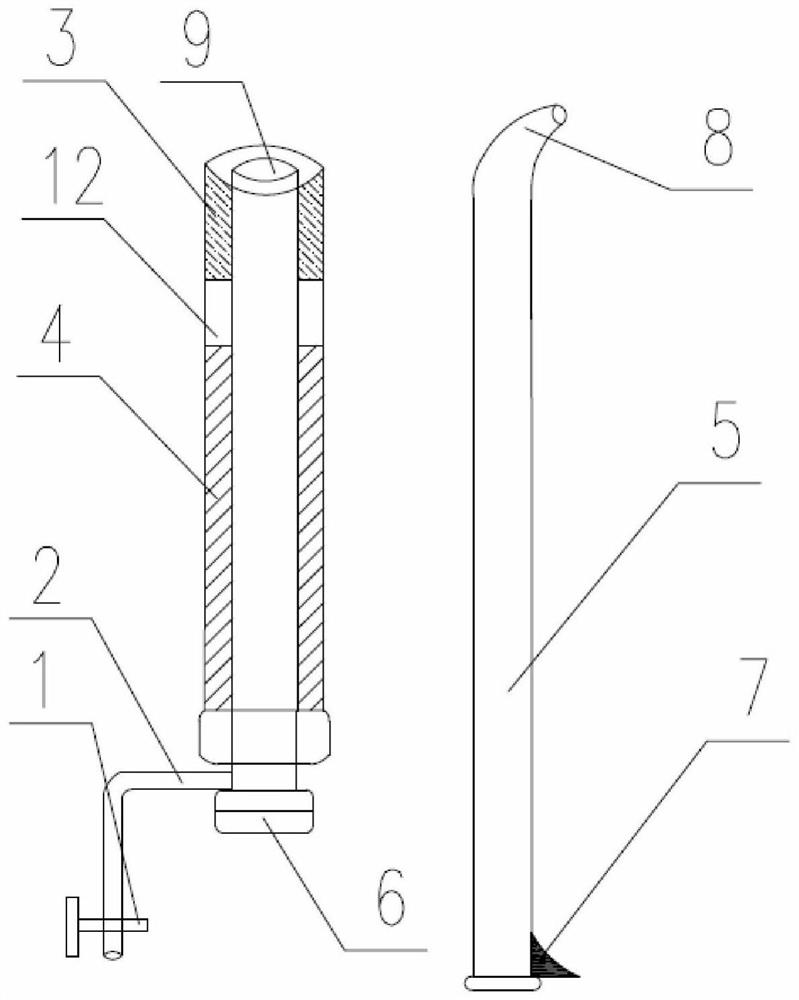
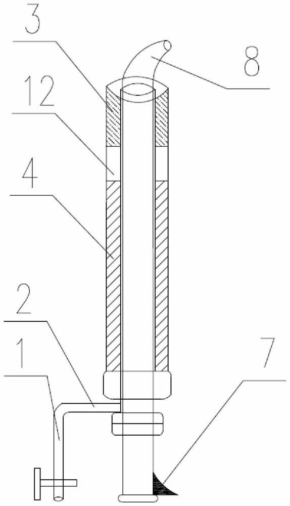
[0025] The invention discloses a two-way leading blood vessel puncture device, see Figure 2-Figure 6 , including the sheath tube wall 4, the catheter sheath tail end sleeve 6 sleeved in the sheath tube wall 4, the anti-corrosion tube that is arranged on the top of the sheath tube wall 4 and connected with the top side wall of the catheter sheath tail end sleeve 6 Cushioned soft membrane 3, sheath water injection pipe 2 arranged at the bottom of catheter sheath tail end sleeve 6, sheath water injection pipe valve 1 arranged on sheath water injection pipe 2, threaded in catheter sheath tail end sleeve 6 And the catheter sheath core 5 for the guide wire 10 to penetrate, the guide part 8 arranged on the top of the catheter sheath core 5, the top of the catheter sheath tail end casing 6 is provided with an outlet 9, and the guide part 8 passes through the outlet 9, The set g...


PUM


Abstract

The invention relates to a two-way guide-in vessel puncture device which comprises a sheath-tube tube wall, a catheter sheath tail end sleeve, an anti-off cushion soft film, a sheath tube water injection pipe, a sheath tube water injection pipe valve, a catheter sheath core and a guide part, wherein the catheter sheath tail end sleeve is sleeved with the sheath-tube tube wall; the anti-off cushionsoft film is arranged at the top of the sheath-tube tube wall and is connected with the side wall of the top of the catheter sheath tail end sleeve; the sheath tube water injection pipe is arranged at the bottom of the catheter sheath tail end sleeve; the sheath tube water injection pipe valve is arranged on the sheath tube water injection pipe; the catheter sheath core is inserted in the catheter sheath tail end sleeve and is used for a guide wire to penetrate; the guide part is arranged at the top end of the catheter sheath core; an outlet is formed at the top end of the catheter sheath tail end sleeve; the guide part penetrates from the outlet; the anti-off cushion soft film is made of a soft material; and hardness of the anti-off cushion soft film is smaller than that of the sheath-tube tube wall. The device can implement a two-way guide catheter sheath in a minimal invasive state of avoiding secondary puncture and an open incision, so that the condition of lesions on both sides can be solved at the same time, puncture times and patient damage are reduced, occurrence of complications is greatly reduced, and surgery efficiency is improved.

Description

technical field [0001] This patent application belongs to the technical field of blood vessel puncture devices, and more specifically relates to a two-way introduction blood vessel puncture device. Background technique [0002] At present, the catheter sheath for vascular puncture is introduced into the catheter sheath in one direction. Through the puncture technology, the catheter sheath is inserted into the catheter sheath to establish a unidirectional channel from the outside to the blood vessel cavity, and the puncture needle is punctured into the artery or vein, and the catheter is inserted into the proximal or distal end. Insert the guide wire, insert the vascular sheath along the guide wire, and establish a passage from the outside to the vascular cavity, but clinically, it is common for patients with lesions on both sides of the puncture point. If you need to solve the bilateral lesions, you need to do two or even multiple punctures Or cut the blood vessel to complet...

Claims


Application Information

Patent Timeline
Patent Type & Authority Applications(China)
IPC IPC(8): A61B17/34
CPCA61B17/3421
Inventor 刘阳李锰
Owner 刘阳
Why Eureka
Try Eureka