Reaction kettle with built-in cooling and heating functions

A technology for reactors and cooling liquids, applied in chemical/physical/physical-chemical stationary reactors, detailed information on chemical/physical/physical-chemical reactors, chemical/physical/physical-chemical processes, etc., which can solve the layout of reactors And the problem of unreasonable reaction rate, uneven temperature of chemical substances, not expanding the volume of the reaction kettle, etc., to shorten the reaction time, increase the stirring effect, and increase the output per unit time.

Pending Publication Date: 2020-09-04
江苏跃华石化工程有限公司
View PDF0 Cites 1 Cited by
  • Summary
  • Abstract
  • Description
  • Claims
  • Application Information

AI Technical Summary

Problems solved by technology

[0002] In chemical production, the use of reactors as reaction vessels to prepare a series of chemical substances has become a common technical means in the industry. However, the existing reactors use external heating or cooling to control the temperature inside the reactors. Due to Reactors are bulky and external heating or cooling can easily lead to uneven temperatures of the internal chemicals, resulting in lower yields of the substances formed after the chemical reaction takes place
[0003] The method of cooling or heating inside the reactor is currently being researched and used by manufacturers. The general idea is to add coils in the reactor to achieve the purpose of controlling the temperature of the solution in the reactor to a certain extent. However, The addition of coils greatly reduces the volume of the reactor with the same volume, regardless of the layout of the reactor and the reaction rate
[0004] In summary, the current technical solution lacks a technical solution that can accurately control the temperature of the solution in the reactor without expanding the volume of the reactor

Method used


Image

  • Reaction kettle with built-in cooling and heating functions
  • Reaction kettle with built-in cooling and heating functions
  • Reaction kettle with built-in cooling and heating functions

Examples


Embodiment Construction

[0035] The following will clearly and completely describe the technical solutions in the embodiments of the present invention. Obviously, the described embodiments are only some of the embodiments of the present invention, rather than all the embodiments. Based on the embodiments of the present invention, all other embodiments obtained by persons of ordinary skill in the art without making creative efforts belong to the protection scope of the present invention.

[0036] The present invention will be further described below in conjunction with specific embodiments and accompanying drawings. It should be understood that the specific embodiments described here are only used to illustrate and explain the present invention, and are not intended to limit the present invention.

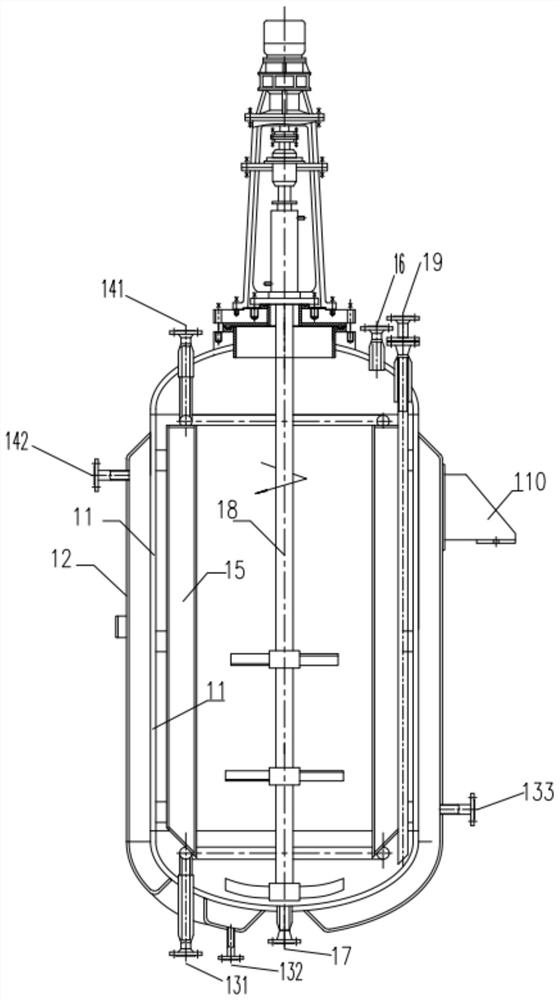
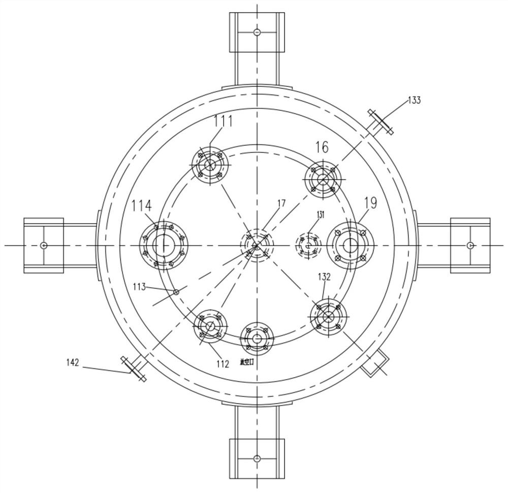
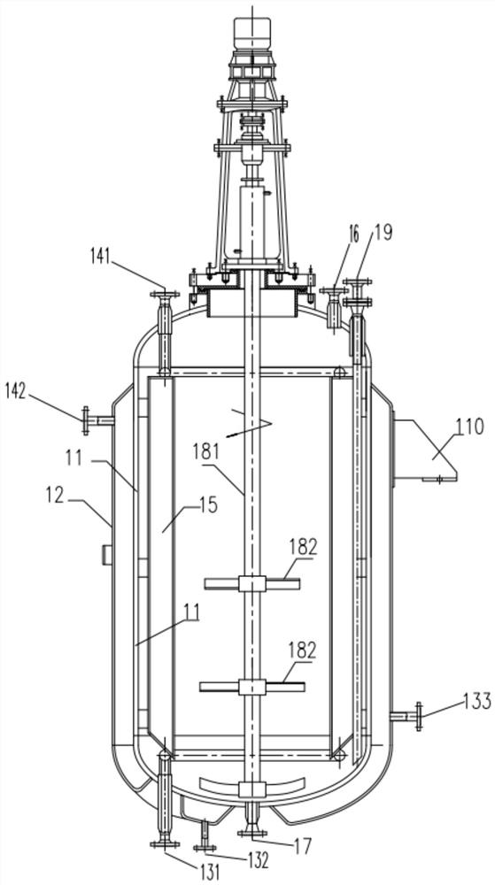
[0037] The embodiment of the present invention discloses a reaction kettle with built-in cooling and heating functions, see figure 1 Shown, described reactor comprises:

[0038] The inner cylinder 11 and ...


PUM


Abstract

The invention provides a reaction kettle with built-in cooling and heating functions. The reaction kettle comprises an inner barrel and a jacket on the outer side of the inner barrel; cooling liquid inlets formed in the bottom and the side wall of the jacket and used for introducing cooling liquid; a cooling liquid outlet formed in the side wall of the jacket at the preset height and the upper part of the inner barrel; a baffle arranged in the inner cylinder, wherein a flow guide pipe is arranged on the baffle, and the flow guide pipe is communicated with the cooling liquid inlet and the cooling liquid outlet; a feeding hole formed in the top of the inner barrel and used for introducing a reaction material; a liquid outlet formed in the bottom of the inner barrel; a stirring system arranged in the inner barrel and used for increasing the reaction rate through stirring; and a discharge hole formed in the top of the inner barrel, wherein when the reaction kettle is heated, the cooling liquid outlet is used as a heating substance inlet, and the cooling liquid inlet is used as a heating substance outlet. According to the scheme, the temperature of the reaction solution in the reactionkettle is accurately controlled, and meanwhile, the volume of the reaction kettle per unit volume is effectively ensured.

Description

technical field [0001] The invention relates to the technical field of reactor equipment, in particular to a reactor with built-in cooling and heating functions. Background technique [0002] In chemical production, the use of reactors as reaction vessels to prepare a series of chemical substances has become a common technical means in the industry. However, the existing reactors use external heating or cooling to control the temperature inside the reactors. Due to Reactors are bulky, and external heating or cooling tends to cause uneven temperatures of the chemicals inside, resulting in lower yields of the substances formed after the chemical reactions take place. [0003] The method of cooling or heating inside the reactor is currently being researched and used by manufacturers. The general idea is to add coils in the reactor to achieve the purpose of controlling the temperature of the solution in the reactor to a certain extent. However, The addition of coils greatly red...

Claims


Application Information

Patent Timeline
Patent Type & Authority Applications(China)
IPC IPC(8): B01J19/18B01J19/00
CPCB01J19/0013B01J19/0053B01J19/006B01J19/0066B01J19/18B01J2219/00058B01J2219/00085B01J2219/00162B01J2219/00245
Inventor 王存明
Owner 江苏跃华石化工程有限公司
Why Eureka
Try Eureka