Quick stamping device for automobile part machining and using method thereof

A technology of stamping device and auto parts, applied in the field of auto parts processing, can solve the problems of workpiece processing failure, no warning device, non-standard molding workpiece, etc., to achieve the effect of ensuring processing quality

Pending Publication Date: 2020-09-04
广西金锋汽车零部件制造有限公司
View PDF0 Cites 7 Cited by
  • Summary
  • Abstract
  • Description
  • Claims
  • Application Information

AI Technical Summary

Problems solved by technology

[0003] Most of the stamping equipment currently on the market is to place the workpiece under the stamping equipment, and then carry out the stamping work. The current stamping equipment does not have a warning device. Once the position of the workpiece is shifted, the stamping equipment is

Method used


Image

  • Quick stamping device for automobile part machining and using method thereof
  • Quick stamping device for automobile part machining and using method thereof
  • Quick stamping device for automobile part machining and using method thereof

Examples


Embodiment 1

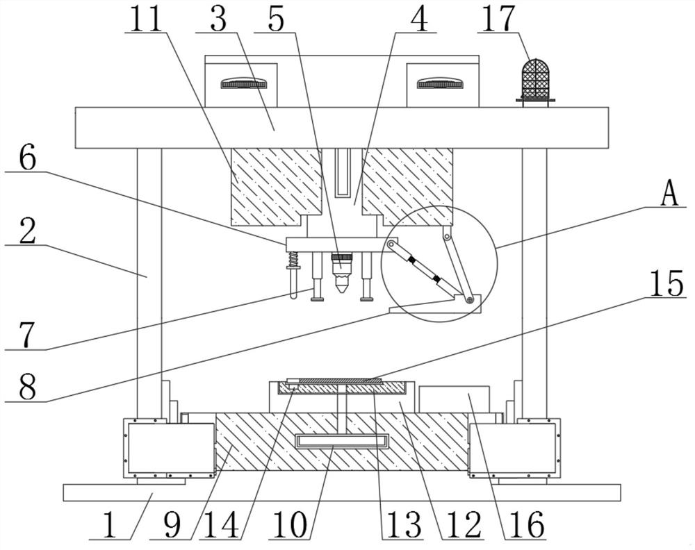
[0031] see figure 1 , figure 2 , image 3 , Figure 4 , Figure 5 with Image 6 , the present invention provides a technical solution:

[0032]A rapid stamping device for processing auto parts and its use method, comprising a base 1 and a support rod 2, the upper end of the base 1 is fixedly connected with a workbench 9, the left and right sides of the workbench 9 are fixedly connected with a support rod 2, and the support rod 2. The upper end faces are all fixedly connected with a top plate 3, and the right side of the upper end face of the top plate 3 is fixedly connected with an alarm lamp 17. The setting of the alarm lamp 17 ensures that when the start button 602 is activated, the alarm lamp 17 plays a role in reminding, and the lower end face of the top plate 3 The center is fixedly connected with a stamping device 4, and the outer side of the stamping device 4 is slidingly connected with a protective frame 11, the upper end surface of the protective frame 11 is fix...

Embodiment 2

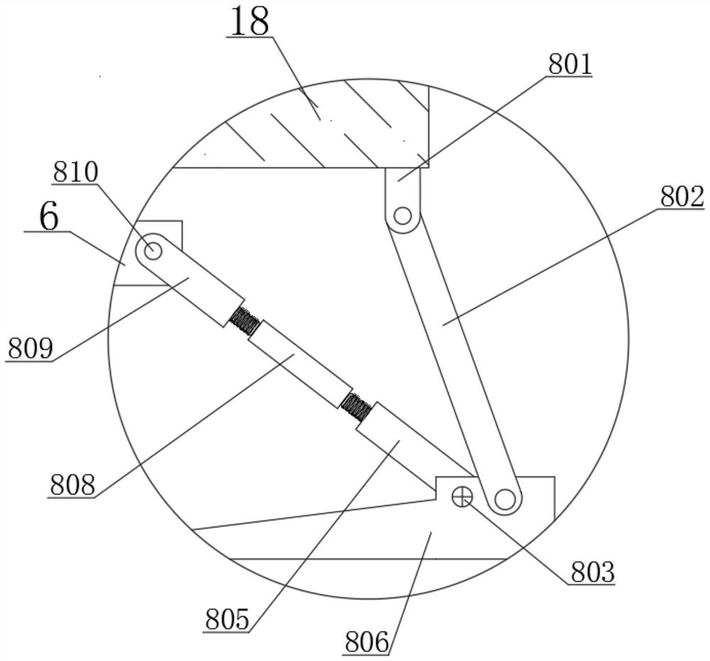
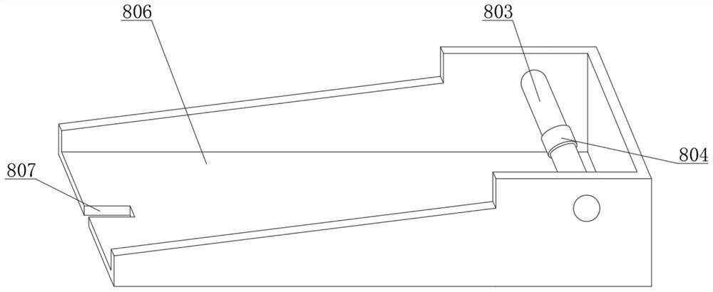
[0040] In embodiment 2, the same part as embodiment 1 will not be repeated, the difference is that when the workpiece 15 is placed in the mold frame 13, when a misalignment occurs, the workpiece 15 and the limiting groove 14 are misaligned at this time, and the guide The rod 604 is in contact with the workpiece 15, and then the guide rod 604 moves upwards to drive the fixed ring 606 to squeeze the telescopic spring 605, and then the guide rod 604 continues to drive the pressing plate 603 to slide upwards, thereby contacting the start button 602, and the start button 602 acts to make the stamping equipment 4 Stop working, and then the alarm lamp 17 lights up to remind people to carry out maintenance work, avoiding the situation of wrong processing, and can drive the upper unit threaded sleeve 809 and the lower unit threaded sleeve 805 to move by rotating the threaded rod 808, thereby can be adjusted according to the actual situation The position of the shovel frame 806 is conven...


PUM


Abstract

The invention relates to the technical field of automobile part machining, in particular to a quick stamping device for automobile part machining and a using method thereof. The device comprises a base and supporting rods, a workbench is fixedly connected with the upper end face of the base, the supporting rods are fixedly connected with the left and right sides of the workbench, a top plate is fixedly connected with the upper ends of the supporting rods, and an alarm lamp is fixedly connected to the right side of the upper end face of the top plate. Stamping equipment is fixedly connected tothe center of the lower end face of the top plate. A protective frame is slidably connected to the outer side of the stamping equipment. In the device, by arranging a pressing plate, a guide rod, a telescopic spring and a fixing ring, when a workpiece is accurately placed in a die frame, the guide rod slides into a limiting groove, and a starting button is not started; and when the workpiece placing position is not accurate, the workpiece is located above the limiting groove, the guide rod moves upwards to extrude the starting button, at the moment, the stamping equipment stops working, the alarm lamp is lightened, people are reminded to perform maintenance work, and the workpiece machining quality is guaranteed.

Description

technical field [0001] The invention relates to the technical field of auto parts processing, in particular to a fast stamping device for auto parts processing and a method for using the same. Background technique [0002] Stamping is to rely on presses and molds to apply external force to plates, strips, pipes and profiles, etc., to cause plastic deformation or separation, so as to obtain workpieces (stamping parts) of required shape and size. Stamping and forging belong to Plastic processing (or pressure processing), collectively known as forging, stamping blanks are mainly hot-rolled and cold-rolled steel plates and steel strips, 60-70% of the world's steel products are plates, most of which are made by stamping Finished products, automobile body, chassis, fuel tank, radiator, boiler drum, container shell, motor, electrical iron core silicon steel sheet, etc. are all stamped. Instruments, household appliances, bicycles, office machinery, There are also a large number of ...

Claims


Application Information

Patent Timeline
IPC IPC(8): B21D37/12B21D43/00B21D43/20B21D22/02B21D53/88B21D55/00B08B1/00
CPCB08B1/001B21D22/02B21D37/12B21D43/003B21D43/20B21D53/88B21D55/00
Inventor 陈木水陈志超凌雪萍陈志开张明乾庞勋凌富浇陈森黎红梅周培峰龙文耀
Owner 广西金锋汽车零部件制造有限公司
Why Eureka
Try Eureka