Feeding device of machine tool
A technology of feeding device and machine tool, which is applied in the field of machine tools, can solve the problems that polygonal bars cannot be automatically fed, and cannot be positioned and fed in the circumferential direction of polygonal bars, and achieves the effects of good consistency and stability.
- Summary
- Abstract
- Description
- Claims
- Application Information
AI Technical Summary
Problems solved by technology
Method used
Image
Examples
Embodiment 1
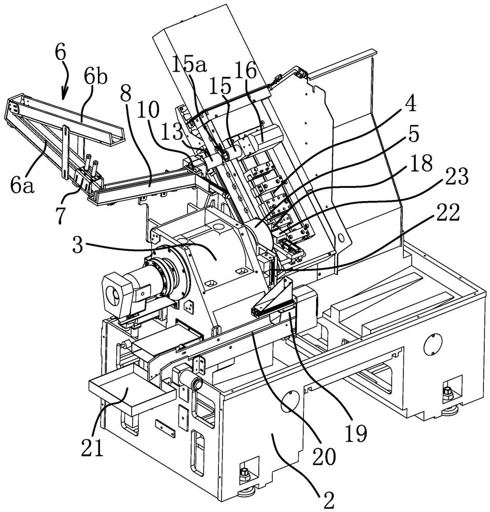
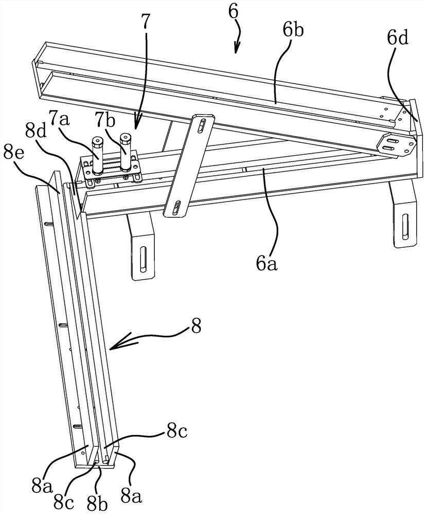
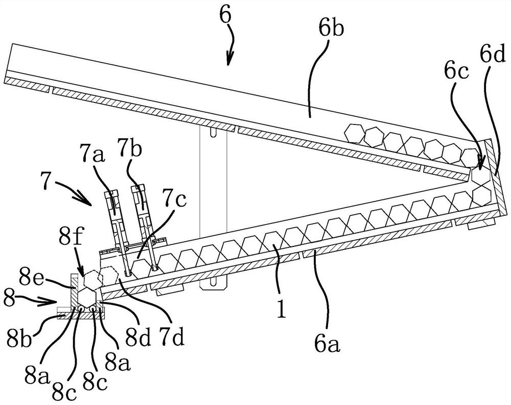
[0051] Such as Figure 1-Figure 6 As shown, a machine tool feeding device is installed on the machine tool for loading and unloading a workpiece 1. The workpiece 1 is a polygonal bar, such as a pentagonal bar, a hexagonal bar, or an octagonal bar. The machine tool includes a bed 2 and an outer cover fixed on the bed 2. A partition is arranged in the outer cover. The outer cover and the partition are not shown in the figure. The bed 2 is provided with a headstock 3 and a carriage assembly 4. The headstock 3 is fixed on the left side of the partition, the carriage assembly 4 is fixed on the right side of the partition, and the spindle box 3 is provided with a spindle clamp 5 for clamping the workpiece 1 . The feeding device of the machine tool includes a feeding mechanism and a blanking mechanism, and the feeding mechanism includes a storage slideway 6, a feeding slideway 8, a material receiving table 9, a positioning member 10, a positioning cylinder 13 and a material receiving...
Embodiment 2
[0062]In the structure of Embodiment 1, the receiving cylinder 15 and the ejecting member 16 are omitted, the positioning cylinder 13 is not fixed on the headstock 3, the positioning cylinder 13 and the pushing member 14 are installed on the carriage assembly 4, and the carriage assembly 4 The positioning cylinder 13 can be driven to move between the main shaft clamp 5 and the material receiving table 9, the material receiving end of the positioning cylinder 13 is located on the right side, the discharge end of the positioning cylinder 13 is located on the left side and can be opposite to the main shaft clamp 5, other structures are the same as The same as in the first embodiment, in order to cooperate with the positioning cylinder 13, the positions of other structures are adaptively installed on the outer cover on the right side of the partition. During processing, after the hexagonal bar material slides into the positioning member 10 from the feeding chute 8, the carriage ass...
Embodiment 3
[0065] In the structure of the second embodiment, the positioning cylinder 13 and the pusher 14 are omitted. The structure of the positioning member 10 is different from that of the second embodiment. The positioning member 10 can be driven to move between the feeding slideway 8 and the spindle clamp 5. The other structures are the same as in the second embodiment, only the installation position of the device on the machine tool is adjusted adaptively, and the machine tool is provided with a tailstock. During processing, after the hexagonal bar slides into the positioning part 10 from the feeding chute 8, the flat pusher 12 moves the positioning part 10 to the spindle fixture 5, and the top of the tailstock pushes the hexagonal bar into the spindle fixture 5 , the spindle clamp 5 clamps the workpiece 1 to complete the loading. The structure of the third embodiment can also complete automatic positioning through the storage slideway 6 and the feeding slideway 8, and maintain th...
PUM
 Abstract
Description
Claims
Application Information
 - R&D
- Intellectual Property
- Life Sciences
- Materials
- Tech Scout
- Unparalleled Data Quality
- Higher Quality Content
- 60% Fewer Hallucinations
Browse by: Latest US Patents, China's latest patents, Technical Efficacy Thesaurus, Application Domain, Technology Topic, Popular Technical Reports.
© 2025 PatSnap. All rights reserved.Legal|Privacy policy|Modern Slavery Act Transparency Statement|Sitemap|About US| Contact US: help@patsnap.com


