Floating support applied to grinding machine

A floating bearing and grinding machine technology, used in the field of bearing processing, can solve the problems of surface roughness not meeting requirements, process requirements, and unqualified products. Effect

Inactive Publication Date: 2020-09-04
SHANDONG LAN YU PRECISION BEARING MFG
View PDF10 Cites 3 Cited by
  • Summary
  • Abstract
  • Description
  • Claims
  • Application Information

AI Technical Summary

Problems solved by technology

[0004] In addition, the support head of the traditional support is made of cemented carbide. After a period of use, the cemented carbide will wear out. When processing the product, the product will be scratched, causing the product to be unqualified, so the cemented carbide should be replaced
In the traditional support, the support head is welded, and it is laborious and time-consuming to replace.

Method used


Image

  • Floating support applied to grinding machine
  • Floating support applied to grinding machine
  • Floating support applied to grinding machine

Examples


Embodiment 1

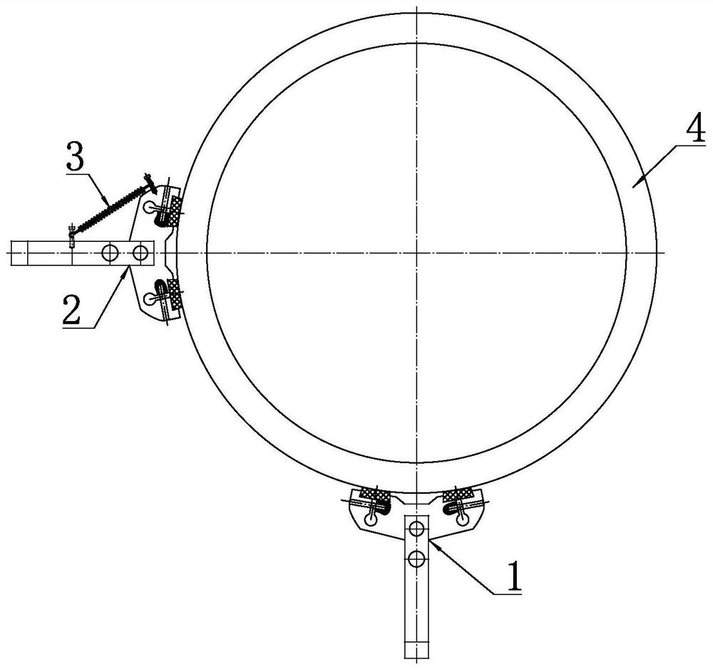
[0042] For the convenience of description, the direction extending along the axial direction of the part 4 to be processed is now defined as the front-rear direction.

[0043] Such as figure 1 As shown, a floating bearing applied to a grinding machine includes a first support assembly 1 and a second support assembly 2, wherein the first support assembly 1 is located on the underside of the part 4 to be processed, and the second support assembly 2 It is located on the left or right side of the part 4 to be processed, and the first support assembly 1 and the second support assembly 2 have the same structure. As a specific implementation, the second support assembly 2 described in this embodiment is arranged on the left side of the part 4 to be processed.

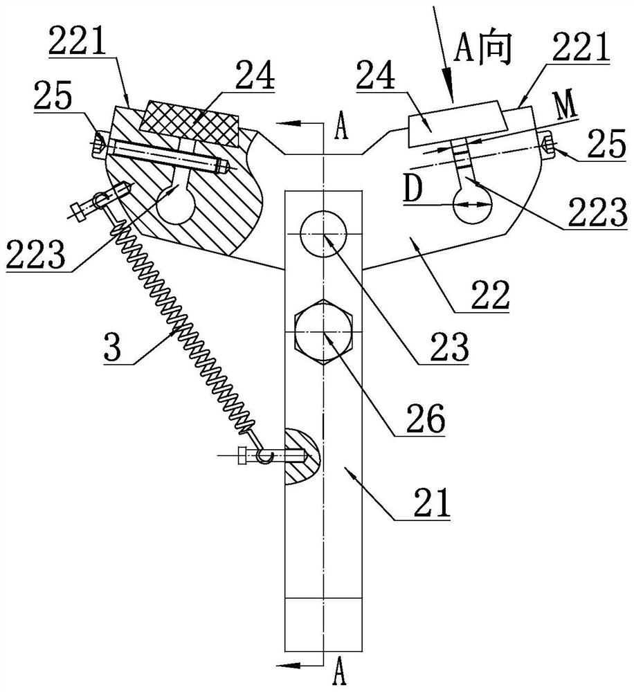
[0044] Here, only the second support assembly 2 is taken as an example to describe its structure in detail.

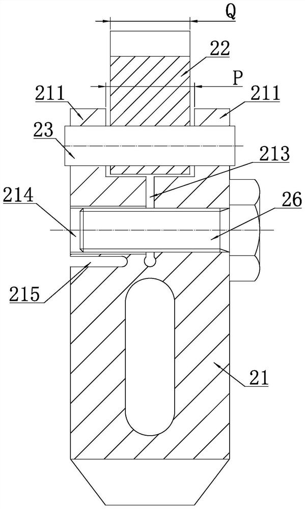
[0045] Such as figure 2 As shown, the second support assembly 2 includes a support rod 21 and a support head 22...

Embodiment 2

[0061] The first expansion joint 223 runs through the support head 22 in a direction perpendicular to the bottom surface of the clamping groove 222, that is, the body of the support head 22 is a separate structure from the clamping part, so Two first locking bolts 25 are arranged between the aforementioned clamping portion and the main body of the support head 22 . All the other structures are the same as in Embodiment 1.


PUM


Abstract

The invention discloses a floating support applied to a grinding machine, and relates to the technical field of bearing machining. The floating support comprises a first supporting assembly located below a part to be machined and a second supporting assembly located on the left side or the right side of the part to be machined, and the first supporting assembly and the second supporting assembly have the same structures. The second supporting assembly comprises a supporting rod and a supporting head arranged at the inner end of the supporting rod, and the middle of the supporting head is hinged to the inner end of the supporting rod. The inner side face of the supporting head is symmetrically provided with supporting bevels regarding the center line of the supporting rod, and the two supporting bevels form a concave structure together. Each supporting bevel is fixedly provided with a supporting block. The floating support can find the machining center of the part automatically, the efficiency of equipment adjustment is greatly improved, the adjustment time of equipment is shortened, and the circle formation effect is good.

Description

technical field [0001] The invention relates to the technical field of bearing processing, in particular to a floating support applied to a grinding machine. Background technique [0002] When the grinding machine grinds the outer circle of the workpiece to be processed, the positioning method adopted is as follows: Figure 6 and Figure 8 shown. Specifically, the end face of the part 4 to be processed is close to the magnetic pole 5 of the grinding machine through the attraction force of the magnetic pole 5, so as to realize the axial fixation of the part 4 to be processed, and the radial fixation of the part 4 to be processed is by setting Two fixed supports 6 are realized, and the outer circle of the workpiece 4 to be processed is ground by a grinding wheel after the axial fixation and the radial fixation are realized. [0003] Such as Figure 6 and Figure 7 As shown, the traditional supports all adopt straight rod-type fixed supports 6, and the support blocks on the ...

Claims


Application Information

Patent Timeline
IPC IPC(8): B24B5/35B24B41/06
CPCB24B5/35B24B41/067
Inventor 林继龙林继泉冯秀雷高君吉
Owner SHANDONG LAN YU PRECISION BEARING MFG
Why Eureka
Try Eureka