Safety control system and method under rail transit train fault
A rail transit train and safety control technology, applied in the field of emergency traction control system, can solve the problems of uncombined traction system availability, slippery slope, train failure to start, etc.
- Summary
- Abstract
- Description
- Claims
- Application Information
AI Technical Summary
Problems solved by technology
Method used
Image

Examples
Embodiment 1
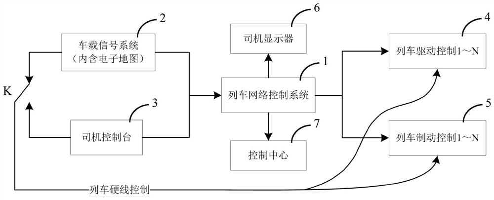
[0055] The structural block diagram of the train control system applied to the safety control system under rail transit train failure described in the embodiment of the present invention is as attached figure 1 Shown. Attached figure 1 The train control system includes the train network control system 1, the on-board signal system 2, the driver console 3, the train drive control unit 4, the train brake control unit 5, the driver display 6 and the control center 7. Control the car, or manually control the car through the driver console 3. Among them, K is the switch between the train in fully automatic driving mode and manual driving mode.
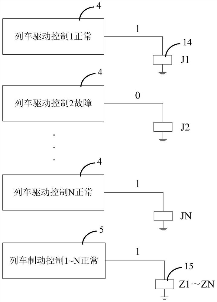
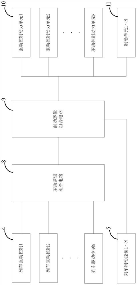
[0056] As attached figure 2 Attached Figure 5 As shown, an embodiment of a safety control system under rail transit train failures specifically includes: a number of train drive control units 4 for outputting drive control signals to corresponding drive control power units 10; and set in the train drive control The output terminal of the un...
Embodiment 2
[0065] Embodiment 1 provides the use of train relay logic combination circuit (ie, drive logic combination circuit 8 and brake logic combination circuit 9) to realize the logic judgment of whether driving / braking conditions are allowed. In addition, in the fully automatic driving system (ATO), since the on-board signal system 2 is used to control the car, the on-board signal system 2 needs to obtain information on whether the emergency traction conditions are met. In this case, the working status of each traction drive / brake control unit can be directly collected through the on-board signal system 2, and the logic combination analysis can be performed through software to determine whether the driving / brake conditions are allowed, and this can be used as the on-board signal system 2 to determine whether it is normal Conditions for entering creep mode. In the fully automatic driving mode, the on-board signal system 2 acts as a driver to control the operation of the rail transit t...
Embodiment 3
[0070] Embodiment 1 provides the use of train relay logic combination circuit (ie, drive logic combination circuit 8 and brake logic combination circuit 9) to realize the logic judgment of whether driving / braking conditions are allowed. In addition, the logic control unit 13 (LCU, Logic Control Unit) can also directly collect the working status of each traction drive / brake control unit, and analyze the logic combination through software to determine whether the drive / brake condition is allowed, as a judgment Whether it is possible to enter the emergency traction permission mode normally. In Embodiment 1, the closing / opening of the auxiliary contact through the relay indicates normality / abnormality of the corresponding train drive / brake control unit. If the emergency traction control of the train is implemented by the logic control unit 13, software logic is used to determine whether the emergency traction condition is allowed.
[0071] As attached Picture 10 As shown, the third...
PUM
 Abstract
Description
Claims
Application Information
 - R&D
- Intellectual Property
- Life Sciences
- Materials
- Tech Scout
- Unparalleled Data Quality
- Higher Quality Content
- 60% Fewer Hallucinations
Browse by: Latest US Patents, China's latest patents, Technical Efficacy Thesaurus, Application Domain, Technology Topic, Popular Technical Reports.
© 2025 PatSnap. All rights reserved.Legal|Privacy policy|Modern Slavery Act Transparency Statement|Sitemap|About US| Contact US: help@patsnap.com