On-line pressure monitoring system for power oil-less equipment
A pressure monitoring and equipment technology, applied in the direction of measuring fluid pressure, measuring devices, instruments, etc., can solve problems such as the need for manual monitoring, difficulty in grasping the health status and changing trends of oil-less equipment, and failures in time, so as to improve safety, The effect of reducing accident rate and preventing loosening
- Summary
- Abstract
- Description
- Claims
- Application Information
AI Technical Summary
Problems solved by technology
Method used
Image

Examples
Embodiment 1
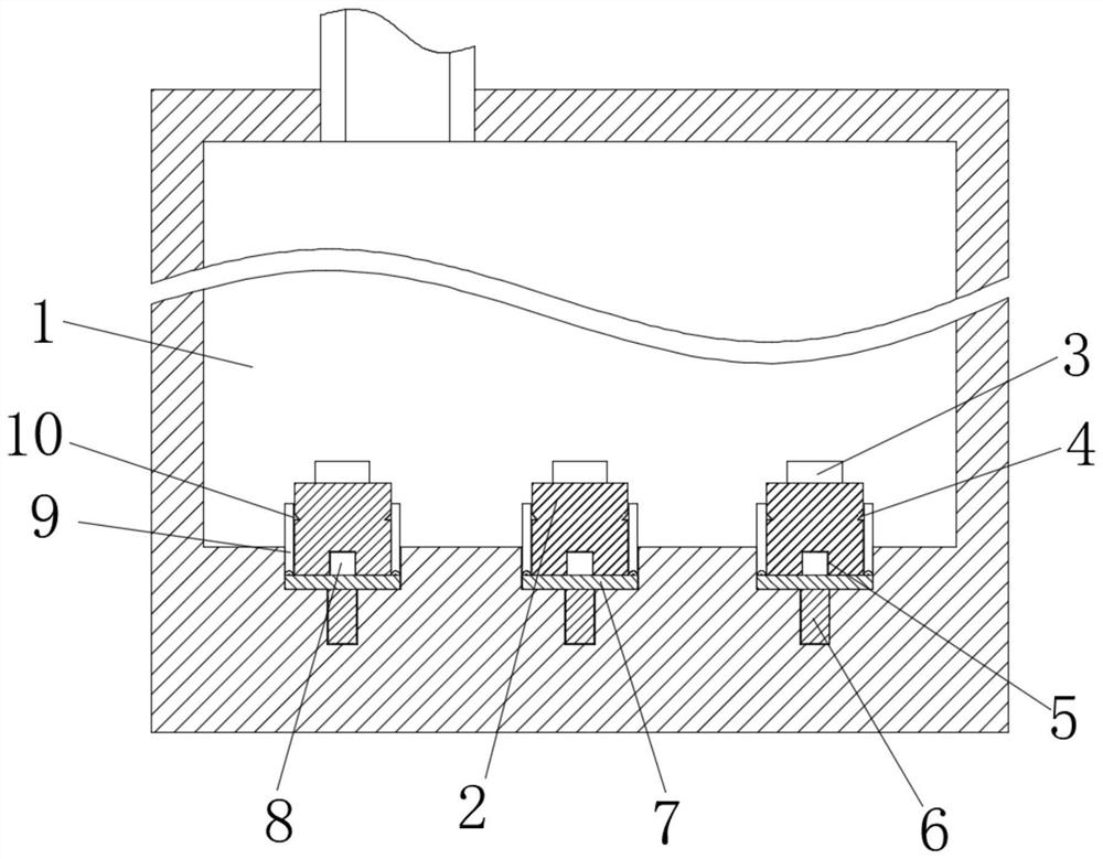
[0024] see figure 1 and Image 6 , the present invention provides a technical solution: an online pressure monitoring system for electric power oil-less equipment, including an oil reservoir 1, a plurality of pressure detection units are arranged inside the oil reservoir 1, and the pressure detection units are located in the oil reservoir 1 Collect pressure parameters inside, the pressure detection unit is electrically connected to a data acquisition terminal, the data acquisition terminal is electrically connected to a wireless transmission device, the wireless transmission device is connected to a central processing unit through a wireless signal, and the data acquisition terminal collects pressure The pressure parameters transmitted by the detection unit supply power to the pressure detection unit at the same time, display the pressure of the pressure detection unit on the spot, and transmit the pressure data to the data concentration unit through the wireless transmission ...
Embodiment 2
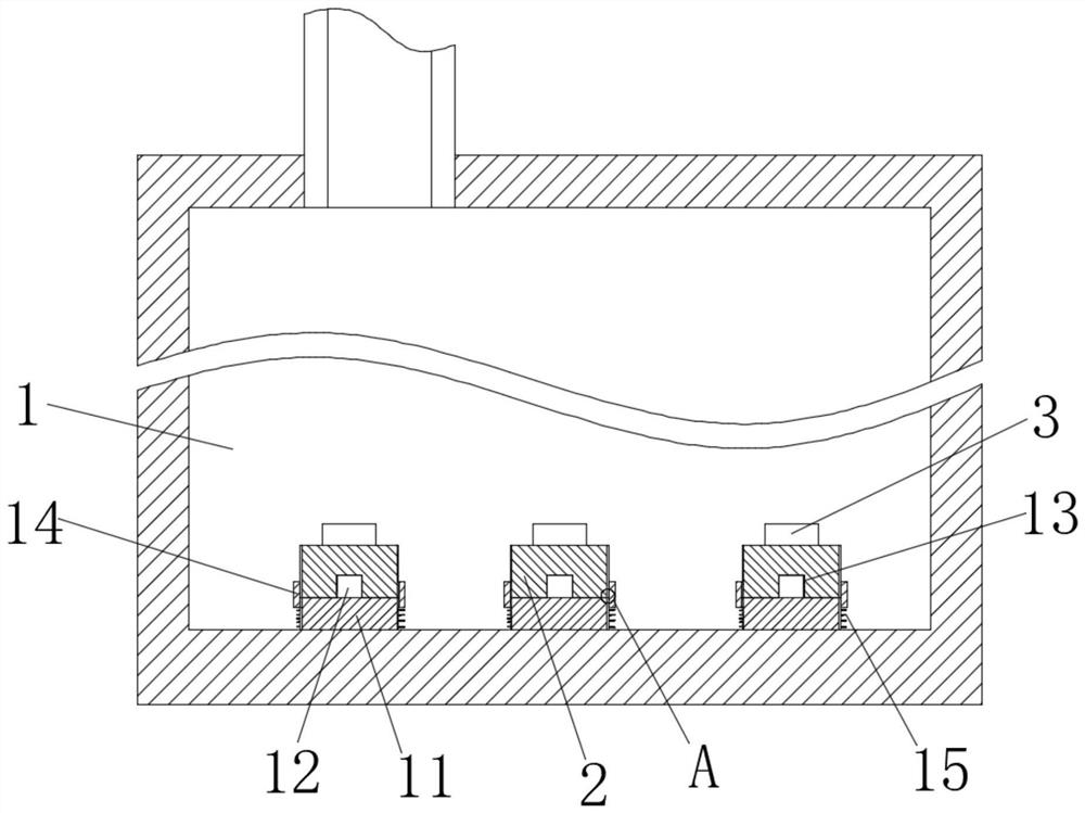
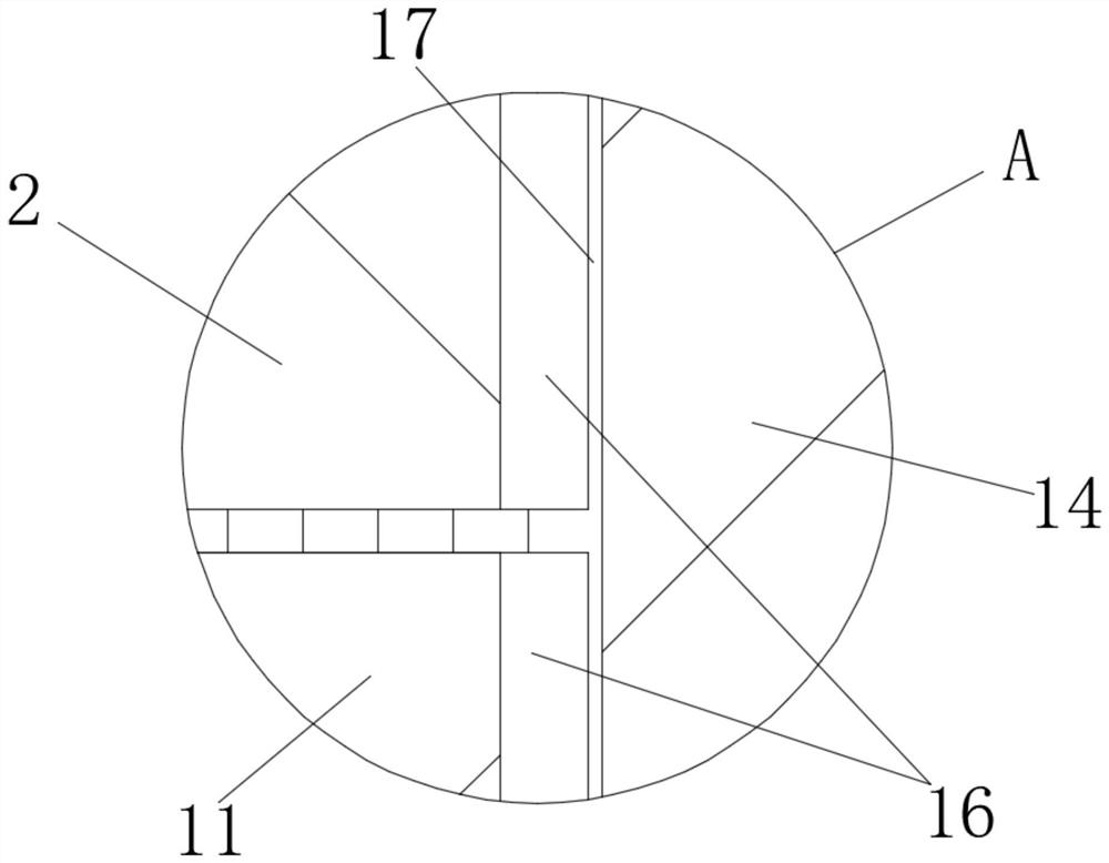
[0029] see figure 2 , image 3 and Image 6 , the difference from Embodiment 1 is that the locking device includes a fixed base 11, a plurality of fixed bases 11 are fixedly connected with the inner bottom surface of the oil reservoir 1 through bolts, and the fixed base 11 is far away from the oil storage A connecting rod 12 is fixedly connected in the middle of the end face of the device 1, and a connecting hole 13 is arranged in the middle of the lower end face of the sensor base 2, and the connecting rod 12 is threadedly connected with the connecting hole 13, and the sensor base 2 is manually rotated to make the sensor base 2 drive The connecting hole is connected with the connecting rod 12. The outer side of the fixed seat 11 and the sensor base 2 is provided with a sliding sleeve 14 to prevent the sensor base 2 from rotating. Between them, a spring A15 is connected to the outer side of the fixed seat 11. When the sensor base 2 is connected with the fixed seat 11 under ...
Embodiment 3
[0033] see Figure 4 , Figure 5 and Image 6 , the difference from Embodiment 1 is that the connecting member includes a sliding hole, and the sliding hole is evenly arranged on the inner side wall of the oil reservoir 1, and a sliding rod 18 is slidably connected in the sliding hole, and the sliding rod The upper end of 18 is fixedly connected with the lower end surface of lifting plate 7, and one side of the outer surface of the limit rod 18 is provided with locking grooves 19 in turn from top to bottom, and the side wall of the oil reservoir 1 is provided with a sliding The working hole connected to the side wall of the hole, the locking post 20 is slidably connected in the working hole, and the locking post 20 cooperates with the locking slot 19. When the sliding rod 18 moves down along the fixed hole, the locking slot 19 Simultaneously move down along the fixing hole, and in the process of moving down again, under the effect of the spring B22, the locking post 20 and t...
PUM
 Abstract
Description
Claims
Application Information
 - R&D
- Intellectual Property
- Life Sciences
- Materials
- Tech Scout
- Unparalleled Data Quality
- Higher Quality Content
- 60% Fewer Hallucinations
Browse by: Latest US Patents, China's latest patents, Technical Efficacy Thesaurus, Application Domain, Technology Topic, Popular Technical Reports.
© 2025 PatSnap. All rights reserved.Legal|Privacy policy|Modern Slavery Act Transparency Statement|Sitemap|About US| Contact US: help@patsnap.com