Exhaust and pressurization combined feeding device and feeding method thereof

A technology of feeding device and feeding method, applied in the directions of transportation and packaging, packaging, plastic recycling, etc., can solve the problems of large amount of compressed air, large amount of compressed air, not stable structure, etc., and achieve high cutting efficiency and operation. The effect of convenience and reasonable structure design

Active Publication Date: 2021-04-27
HANGZHOU FUYANG DONGSHAN PLASTIC MACHINERY
View PDF8 Cites 0 Cited by
  • Summary
  • Abstract
  • Description
  • Claims
  • Application Information

AI Technical Summary

Problems solved by technology

At present, the feeding device of the molding machine still has the problem that the feeding speed is relatively slow and it is prone to blockage
[0003] The Chinese patent with the publication number CN211440856U discloses a material tank of an EPS foam molding machine. In this patent, a compressed air inlet and a discharge port are respectively arranged at both ends of the pressurized barrel, so that the EPS foam particles are directed towards the discharge under the impact of compressed air. In this way, the amount of compressed air is more, which wastes energy; the Chinese patent with the publication number CN206733458U discloses a kind of EPS molding machine material tank, when the material tank in the patent is fed, EPS foam particles enter the material through the feed port The barrel is pressurized by inputting compressed air into the barrel through the compressed air inlet, and the baffle plate is driven to rotate through the rotating cylinder. When the opening of the sealing plate corresponds to the opening of the baffle plate, the material is unloaded. Not only the amount of compressed air is large, but also The baffle plate is driven to rotate by the rotating cylinder, and the structure is not stable enough

Method used


Image

  • Exhaust and pressurization combined feeding device and feeding method thereof
  • Exhaust and pressurization combined feeding device and feeding method thereof
  • Exhaust and pressurization combined feeding device and feeding method thereof

Examples


Embodiment Construction

[0034] The present invention will be further described in detail below in conjunction with the accompanying drawings and examples. The following examples are explanations of the present invention and the present invention is not limited to the following examples.

[0035] Example.

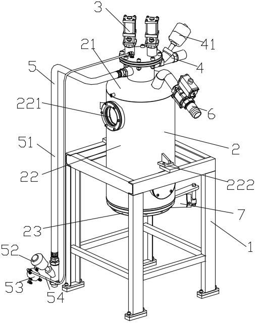
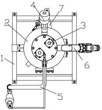
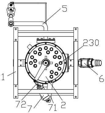
[0036] see Figure 1 to Figure 8 , the feeding device combined with exhaust and pressurization in the present embodiment includes a frame 1, a feed barrel 2, a vent valve 3, a negative pressure valve 4, a pressurizing mechanism 5, a feed pipe 6 and a cylinder 7; The barrel 2 is installed on the frame 1; the vent valve 3, the negative pressure valve 4 and the feed pipe 6 are all installed on the feed barrel 2; one end of the cylinder 7 is provided with a fixing part 71, and the other end is provided with a connecting part 72; The fixing part 71 is fixedly connected with the base 235 ; the connecting part 72 is rotatably connected with the connecting rod 236 .

[0037] The pressurization mechanism ...


PUM


Abstract

The invention relates to an exhaust and pressurization combined feeding device and a feeding method thereof. In order to solve the problems that a feeding device in the prior art is slow in material falling and prone to blockage, the following technical scheme is provided: the exhaust and pressurization combined feeding device comprises a rack, a feeding barrel, an emptying valve, a negative pressure valve, a pressurization mechanism, a feeding pipe and an air cylinder. The feeding barrel is mounted on the rack. The emptying valve, the negative pressure valve and the feeding pipe are all mounted on the feeding barrel. The pressurizing mechanism comprises a pressurizing pipe, a pressurizing balance valve, a pressure sensor and a pressure feedback pipe. The pressurizing pipe is connected with the feeding barrel. The pressurizing balance valve is mounted on the pressurizing pipe. The pressure sensor is mounted on the pressurizing balance valve. One end of the pressure feedback pipe is connected with the feeding barrel, and the other end is connected with the pressure sensor. The feeding barrel sequentially comprises an upper cover, a barrel body and a lower cover from top to bottom, the upper cover and the lower cover are fixedly connected with the barrel body, and a discharge hole is formed in the lower cover. The exhaust and pressurization combined feeding device and the feeding method thereof are fast in material falling, not prone to blockage and capable of saving energy.

Description

technical field [0001] The invention relates to a feeding device and a feeding method thereof, in particular to a feeding device combining exhaust and pressurization and a feeding method thereof, mainly used in EPS foam forming machines. Background technique [0002] The EPS foam molding machine is a mechanical device that processes EPS foam particles into products of a certain shape. The processing process is to first put the EPS foam particles into a mold cavity, and then pass in steam for a certain period of time to bond the EPS foam particles into a mold. Integrate to form EPS foam products. In the production process, it is necessary to feed the raw materials into the feeding device first, and then send the raw materials into the mold cavity through the material gun. At present, the feeding device of the molding machine still has the problems of relatively slow feeding speed and easy blockage. [0003] The Chinese patent with the publication number CN211440856U disclose...

Claims


Application Information

Patent Timeline
Patent Type & Authority Applications(China)
IPC IPC(8): B65G53/28B65G53/66B65G53/58B65G53/36B65D88/70B65D90/54B65D90/48B29C44/36
CPCB65G53/28B65G53/66B65G53/58B65G53/36B65D88/70B65D90/54B65D90/48B29C44/36Y02W30/62
Inventor 徐元朝
Owner HANGZHOU FUYANG DONGSHAN PLASTIC MACHINERY
Why Eureka
Try Eureka