
Device and method for detecting performance of linear guide rail pair clamp

A technology of linear guide pair and detection device, which is applied in the field of CNC machine tools, can solve the problems that the problems have not been well solved, there is no clamp performance detection, and the test device and test method have not been standardized.

Pending Publication Date: 2020-09-04
JILIN UNIV
View PDF3 Cites 0 Cited by
  • Summary
  • Abstract
  • Description
  • Claims
  • Application Information

AI Technical Summary

Problems solved by technology

[0002] Linear guide rails have a wide range of applications, but their existing problems have not been well resolved
[0004] At the same time, the specific test device and test method have not been standardized, and there are few patents on the clamper performance detection device. Most of the patents on the clamper that can be found at present are patents for the improvement of the clamper structure, such as patent numbers: 201620285445.3 and 201720444606.3, they only improved the structure of the clamp, and did not test the performance of the clamp
Patent 201510703893.0 is about a device for detecting the reaction time and response time of the clamp for rail pairing and its measurement method. It has great limitations. It does not write the loading part of the clamp, and the function of the detection part is also very single. It only Can detect reaction time and response time

Method used


Image

  • Device and method for detecting performance of linear guide rail pair clamp
  • Device and method for detecting performance of linear guide rail pair clamp
  • Device and method for detecting performance of linear guide rail pair clamp

Examples


Embodiment 1

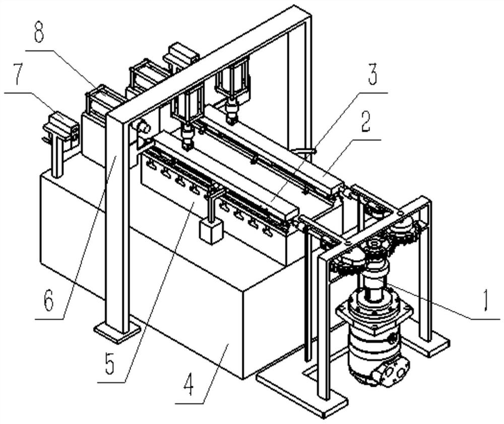
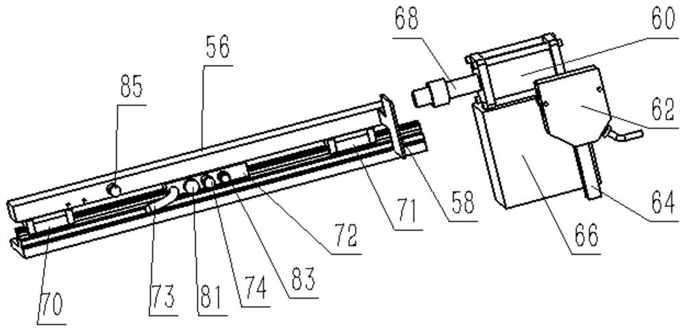
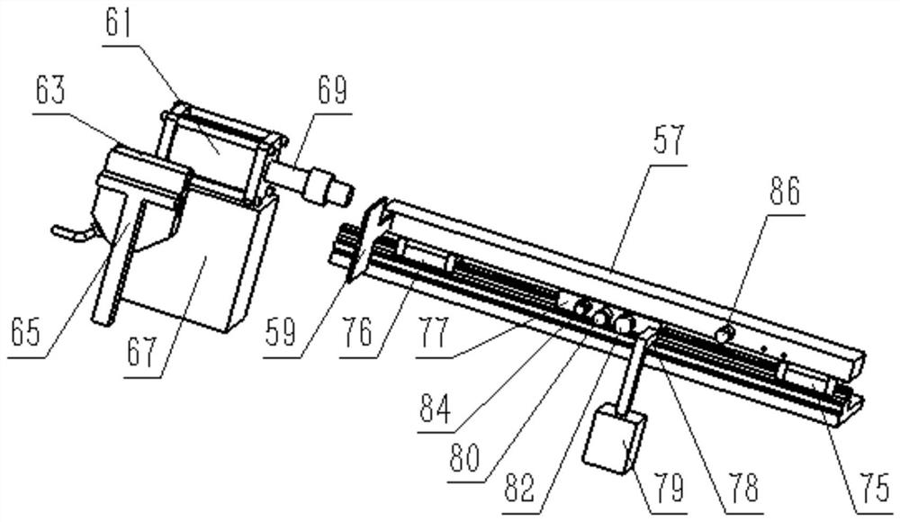
[0135] as attached figure 1 As shown, it is a schematic structural diagram of a detection device for the performance of a linear guide rail auxiliary clamp provided by an embodiment of the present invention, including a workbench mechanism for installing a hydraulic clamp 72 and / or a manual clamp 77, said The detection device also includes:

[0136] An axial loading mechanism 1 provided with an axial loading detection assembly is used to apply axial dynamic and / or static loads to the workbench mechanism; the axial loading detection assembly is used to detect the applied axial dynamic and / or static loads. / or static loads;

[0137] A longitudinal loading mechanism 6 provided with a longitudinal loading detection assembly is used to apply a longitudinal dynamic and / or static load to the workbench mechanism; the longitudinal loading detection assembly is used to detect the applied longitudinal dynamic and / or static load;

[0138] The performance detection mechanism is used to ...

Embodiment 2

[0254] An embodiment of the present invention provides a method for detecting the performance of a linear guide rail sub-clamp. The detection method includes the following steps:

[0255] Install the hydraulic clamp 72 and / or the manual clamp 77 on the workbench mechanism;

[0256] Applying dynamic and / or static loads to the workbench mechanism through the axial loading mechanism 1 and / or the longitudinal loading mechanism 6;

[0257] The hydraulic clamp 72 and / or the manual clamp 77 are detected by the performance detection mechanism.

[0258] Specifically, the linear guide rail vice clamp performance testing is divided into: clamp response time detection, clamp maximum holding force detection, clamp braking distance detection, clamp acceleration detection when braking, clamp wear detection and clamp temperature detection.

Embodiment 3

[0260] The embodiment of the present invention provides a detection method of the response time of the clamp according to embodiment 2, and the detection method includes the following steps:

[0261] S101, install a hydraulic clamp 72 or a manual clamp 77 according to the type of clamp to be detected;

[0262] S102, according to the simulated loading condition of the clamp, install the axial loading mechanism 1 and the longitudinal loading mechanism 6, if it is no-load condition, do not install the loading part;

[0263] S103, install the clamper reaction time detection assembly, install the first acceleration vibration sensor 74 on the side of the hydraulic clamp 72, install the second acceleration vibration sensor 80 on the side of the manual clamping fixture 77, and install the first acceleration vibration sensor 74 and The data transmission line of the second acceleration vibration sensor 80 is connected with the computer equipment, and debugs the corresponding data acquis...


PUM


Abstract

The invention is applicable to the field of numerical control machine tools, and provides a device and a method for detecting the performance of a linear guide rail pair clamp. The detection device comprises: a workbench mechanism used for installing the clamping device; an axial loading mechanism that is provided with an axial loading detection assembly; a longitudinal loading mechanism which isprovided with a longitudinal loading detection assembly; and a performance detection mechanism which is used for detecting the clamp. The detection device can be used for detecting the performance ofthe clamp by simulating the actual machining working condition of a machine tool and collecting signals, analyzing the reliability and precision of the clamp under load and predicting the failure of the clamp to a certain extent.

Description

technical field [0001] The invention belongs to the field of numerical control machine tools, and in particular relates to a detection device and a detection method for the performance of a linear guide rail auxiliary clamp. Background technique [0002] Linear guide rails have a wide range of applications, but their existing problems have not been well resolved. The linear guide pair is in point or line contact, and the vibration damping performance is relatively poor; in the traditional machining process, the cutting force and impact load of the tool are mainly borne by the screw, which seriously affects the life and accuracy of the screw; the workpiece in the vertical direction During the upper processing, in case of unexpected situations such as power outages, the workpiece is prone to fall, causing serious safety accidents such as machine crashes and human deaths; when the linear motor is used in conjunction with the linear guide rail, since there is no braking function...

Claims


Application Information

Patent Timeline
Patent Type & Authority Applications(China)
IPC IPC(8): G01M13/00
CPCG01M13/00
Inventor 杨兆军池佳伟陈传海刘勇刚田海龙罗巍于立娟朱晓翠
Owner JILIN UNIV
Learn More