
Non-cooperative target laser induced deviation distance measuring system and method

A measurement system and distance measurement technology, used in radio wave measurement systems, satellite radio beacon positioning systems, measurement devices, etc., can solve problems such as explosions, different theoretical decoupling distances and actual decoupling distances, and achieve high solution accuracy. Effect

Active Publication Date: 2020-09-04
ROCKET FORCE UNIV OF ENG
View PDF4 Cites 2 Cited by
  • Summary
  • Abstract
  • Description
  • Claims
  • Application Information

AI Technical Summary

Problems solved by technology

However, under special circumstances such as local occlusion or specular reflection points in the laser propagation path, the decoy laser reflection point does not coincide with the theoretical decoy point; and when the theoretical decoy point is a non-rigid target in the air such as the canopy in the jungle , the laser weapon will pass through the non-rigid target in the air and continue to fly downward until it explodes on the ground; the above two situations will lead to the difference between the theoretical decoy distance and the actual decoy distance, and the problem of how to measure the actual decoy distance is still waiting for solution

Method used


Image

  • Non-cooperative target laser induced deviation distance measuring system and method
  • Non-cooperative target laser induced deviation distance measuring system and method
  • Non-cooperative target laser induced deviation distance measuring system and method

Examples


Embodiment Construction

[0030] Embodiments of the present invention will be described in further detail below in conjunction with the accompanying drawings.

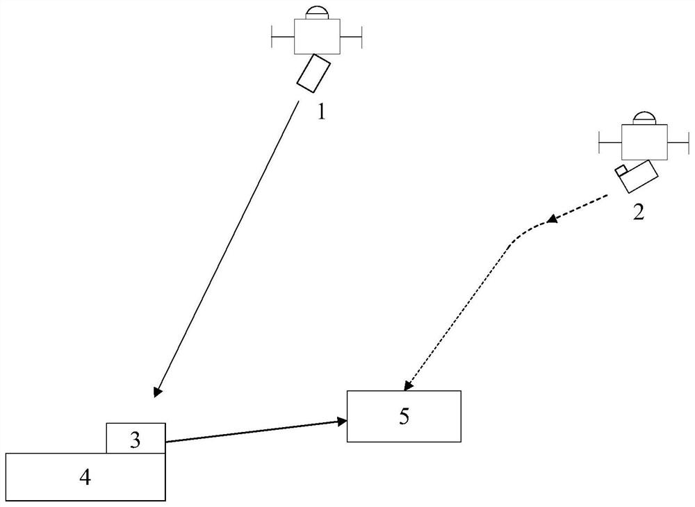
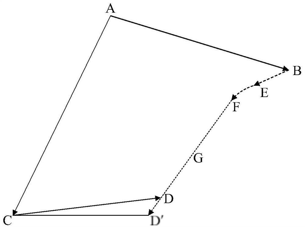
[0031] combine figure 1 with figure 2 , the laser decoy principle of the present invention is analyzed as follows:

[0032] At the initial moment, the positions of UAV 1 and UAV 2 are points A and B respectively, and the position of real target 4 is point C. First, the laser target indicator 8 on the UAV 1 emits an indicating laser, the laser irradiates the real target 4 and part of the laser light is reflected by it, the laser seeker 11 on the UAV 2 detects the reflected laser light and then determines the real target 4, and fly towards it along the direction of BC; the laser decoy device 3 on the real target 4 detects the indicating laser and decodes it, and then emits the same coded decoy laser along the direction of the false target to the decoy laser reflection point 5, The position is point D; when the UAV 2 flies to point E, the lase...


PUM


Abstract

The invention relates to a non-cooperative target laser induced deviation distance measuring system and method. The system is composed of an unmanned aerial vehicle 1, an unmanned aerial vehicle 2 anda non-cooperative target. The method comprises the following seven steps: determining a conversion matrix from an earth-centered earth-fixed coordinate system to a local northeast sky coordinate system taking a main antenna as an original point; measuring the distance between a slave antenna and a true target; solving the relative azimuth vector of a master antenna and the true target; enabling the unmanned aerial vehicle 2 to continuously fly to a deviation inducing laser reflection point along a straight line; obtaining a heading unit vector; obtaining the relative azimuth vector of the master antenna and the deviation inducing laser reflection point; and evaluating the actual deviation inducing effect. Compared with the prior art, the method has the advantages that no auxiliary information of the target needs to be provided, and measurement can be achieved only through existing equipment on the unmanned aerial vehicles; and the solving precision of the relative azimuth vector basedon satellite carrier phase observation data is higher.

Description

technical field [0001] The present invention relates to the technical field of photoelectric countermeasure effect evaluation, relates to a non-cooperative target laser decoy distance measurement system and method, in particular to a non-cooperative target laser decoy distance measurement system and method based on satellite relative positioning. Background technique [0002] The semi-active laser-guided weapon uses the target designator to emit an indicating laser to the target, and the laser seeker receives the indicating laser reflected or scattered by the target, determines the position information of the target, and then strikes it precisely. Satellite navigation equipment is small in size and can be easily integrated into UAVs. Satellite navigation has the advantage of being all-weather and all-weather, which can meet the needs of real-time positioning. The relative positioning technology of short-baseline satellites is mature, and the measurement accuracy is high. It ...

Claims


Application Information

Patent Timeline
Patent Type & Authority Applications(China)
IPC IPC(8): G01S11/12G01S19/43G01S19/45
CPCG01S11/12G01S19/43G01S19/45
Inventor 蔡伟侯雨果杨志勇李敏侯传勋李洪才
Owner ROCKET FORCE UNIV OF ENG
Learn More