Metal reflector and manufacturing method thereof

A technology for a metal mirror and a manufacturing method, applied in the field of mirrors, can solve the problems of low weight reduction rate, etc., and achieve the effects of improving the bonding strength, shortening the process flow, and reducing the second single-point turning process

Active Publication Date: 2020-09-04
CHANGCHUN INST OF OPTICS FINE MECHANICS & PHYSICS CHINESE ACAD OF SCI
View PDF8 Cites 6 Cited by
  • Summary
  • Abstract
  • Description
  • Claims
  • Application Information

AI Technical Summary

Benefits of technology

This technology allows for flexibility in adding layers on metals without making them heavier by reducing their thickness or increasing its density. It achieves this through modifying certain properties such as reflectivity, coloring agents, crystal orientation, etc., resulting in improved optical performance compared with previous methods like plasma spray coatings. Additionally, there are technical benefits associated with removing unwanted materials during production instead of relying solely upon grinding techniques. Overall, these improvements improve the quality control and efficiency of producing laminated structures made up entirely of different types of material together.

Problems solved by technology

This patented technical solution involves reducing the size or thickness of certain parts within an optoelectrooptic device's lens assembly without compromising its performance. By doing away with conventional techniques like millings, drilling, etchants, etc., these new ways allow for better control over how much space they require while still maintaining their desired properties.

Method used


Image

  • Metal reflector and manufacturing method thereof
  • Metal reflector and manufacturing method thereof
  • Metal reflector and manufacturing method thereof

Examples


Embodiment Construction

[0042] In order to enable those skilled in the art to better understand the solutions of the present invention, the following will clearly and completely describe the technical solutions in the embodiments of the present invention in conjunction with the drawings in the embodiments of the present invention. Obviously, the described embodiments are only It is an embodiment of a part of the present invention, but not all embodiments. Based on the embodiments of the present invention, all other embodiments obtained by persons of ordinary skill in the art without making creative efforts shall fall within the protection scope of the present invention.

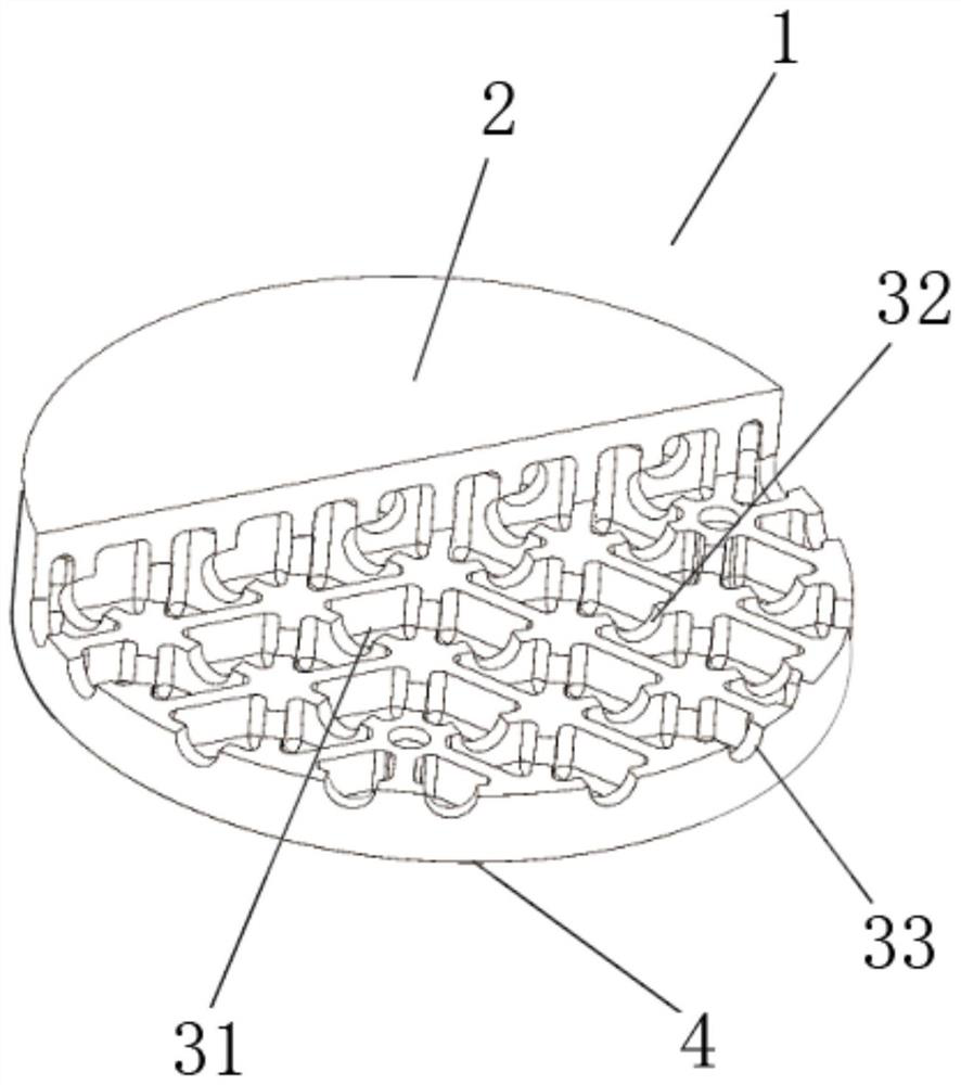
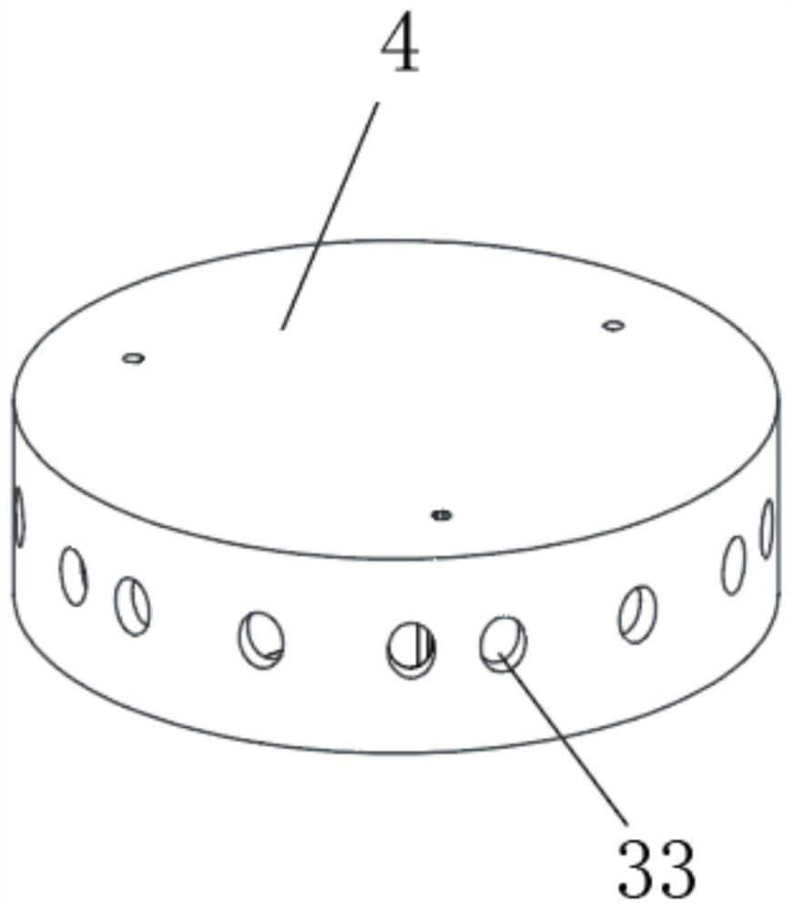
[0043] Such as figure 1 and Figure 5 As shown, a metal reflector includes a closed base 1 and a mirror 2 arranged on one end surface of the base 1, an internal sandwich lightweight structure and a back plate 4 on the other end surface; the mirror 2 includes surface modification layer 11 , reflective layer 12 and protective layer ...


PUM


Abstract

The invention discloses a metal reflector which comprises a closed substrate, a mirror surface arranged on the surface of one end of the substrate, an internal interlayer lightweight structure and a back plate arranged on the surface of the other end of the base body. The mirror surface comprises a surface modification layer, a reflecting layer and a protective layer, and the protective layer is the outermost layer; the interlayer lightweight structure comprises a plurality of cavities and through holes connected through the cavities. An additive manufacturing and processing technology is adopted, so that the interlayer light-weight structure in the metal reflector is more flexible, the metal reflector not only meets the high-rigidity design of the reflector, but also is light in weight due to the interlayer light-weight structure; the integrated design is adopted; the design of the surface modification layer enables the precision to be defined as that the RMS value of the deviation value between the precision and an ideal surface is superior to 1/10 lambda, wherein lambda is equal to 632.8 nm; the design of the transition layer enhances the chemical and mechanical durability of the metal reflector, and improves the bonding strength between the metal reflector substrate and the surface modification layer.

Description


Claims


Application Information

Patent Timeline
Owner CHANGCHUN INST OF OPTICS FINE MECHANICS & PHYSICS CHINESE ACAD OF SCI
Why Eureka
Try Eureka