
Composite circulating current suppression method and device for shore power supply system

A shore power supply and circulating current suppression technology, which is applied to output power conversion devices, electrical components, and conversion equipment for intermediate conversion to DC conversion, etc. Output voltage drop, unsatisfactory suppression of low-frequency circulating current, etc., to achieve the effects of low cost, easy capacity expansion, and high reliability

Active Publication Date: 2020-09-04
XJ POWER CO LTD +3
View PDF10 Cites 1 Cited by
  • Summary
  • Abstract
  • Description
  • Claims
  • Application Information

AI Technical Summary

Problems solved by technology

[0004] Circulation suppression methods include hardware elimination method and software control method. The hardware circulation elimination method can prevent the generation of the circulation path on the hardware, and it is usually realized by adding an isolation transformer at the output port of each parallel-connected shore power variable frequency power supply device, but this will Resulting in a larger size and weight for the shore power system
It is also possible to suppress the circulating current through the series reactor at the output end of the shore power supply unit. The series reactor can provide high impedance for each shore power supply unit to suppress the circulating current, but this method is not ideal for suppressing low-frequency circulating current, and Because the impedance is increased, the output voltage drop of the shore power supply is increased, and the energy conversion efficiency is reduced.

Method used


Image

  • Composite circulating current suppression method and device for shore power supply system
  • Composite circulating current suppression method and device for shore power supply system
  • Composite circulating current suppression method and device for shore power supply system

Examples


Embodiment Construction

[0038] In order to make the object, technical solution and advantages of the present invention clearer, the present invention will be further described in detail below in combination with specific embodiments and with reference to the accompanying drawings. It should be understood that these descriptions are exemplary only, and are not intended to limit the scope of the present invention. Also, in the following description, descriptions of well-known structures and techniques are omitted to avoid unnecessarily obscuring the concept of the present invention.

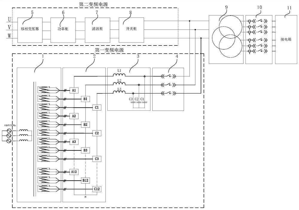
[0039] One aspect of the present invention provides a composite circulation suppression method for a shore power supply system. The shore power supply system includes n shore power supplies connected in parallel, where n is an integer greater than 1; the method includes the following steps:

[0040] In step S100, the average current control is adopted for each shore power supply to generate modulation degree compensation....


PUM


Abstract

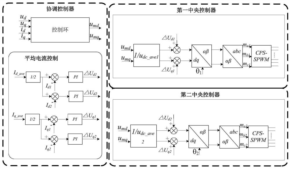
The invention discloses a composite circulating current suppression method and device for a shore power supply system, which can solve the problem of circulating current in a shore power supply parallel system. The composite circulating current suppression method comprises a circulating current suppression method based on the combination of average current control and centralized control, and theamplitude, frequency and phase of the output voltage of a shore power supply are controlled through a current equalization control method in the control process. The centralized control is realized through a coordination controller, the dq coordinate system modulation waves are uniformly generated and are issued to each variable frequency power supply central controller, each central controller receives the dq axis modulation waves Umd, and Umq is divided by the average value of the direct current bus voltage of each variable frequency power supply and then is superposed with the compensationamount generated by the current equalization control to achieve the purpose of circulating current suppression of the parallel shore power systems, so that the stable operation of the shore power systems is guaranteed. In addition, the composite circulating current suppression device for a shore power supply system is easy to implement and has the advantages of being low in cost and high in reliability, being easy to expand and the like.

Description

technical field [0001] The invention relates to the technical field of shore power, in particular to a compound circulation suppression method and device for a shore power power supply system. Background technique [0002] Due to the limitation of the power of power semiconductor devices, the power level that can be achieved by a single shore power variable frequency power supply device is difficult to adapt to high power level applications. Therefore, in high power applications, shore power supply devices are generally used in parallel to improve the system. Capacity and redundancy; at the same time, this parallel method is simple and easy to expand, so it has been widely researched and applied. [0003] Shore power supplies are connected in parallel to output AC voltage. To achieve parallel operation of two or more shore power supplies, the frequency, phase, amplitude and internal resistance of the output voltages of each device are exactly the same, so that the output cur...

Claims


Application Information

Patent Timeline
Patent Type & Authority Applications(China)
IPC IPC(8): H02J3/38H02J3/46H02M5/40H02M5/458
CPCH02J3/38H02J3/46H02M5/40H02M5/458H02M1/0038
Inventor 马骏王翼宋晓梅刘玉振李正力王先为冯宇鹏来璐陈旭东高洪
Owner XJ POWER CO LTD
Learn More