
Engineering garbage treatment equipment for building

A technology of waste treatment equipment and engineering, applied in the engineering field of construction, can solve the problems of inconvenient waste treatment, polluted land, and construction waste cannot be effectively treated, and achieves the effect of increasing stability and good use effect.

Inactive Publication Date: 2020-09-08
深圳市兰锋科技有限公司
View PDF13 Cites 0 Cited by
  • Summary
  • Abstract
  • Description
  • Claims
  • Application Information

AI Technical Summary

Problems solved by technology

[0002] With the acceleration of urbanization, the construction industry has also developed rapidly. However, in the process of construction, a large amount of construction waste will be generated. These construction wastes are difficult to degrade by themselves, and if they are landfilled, they will pollute Land, so that the land can only be abandoned for a long time, causing great pollution to the environment, and currently there is no device for processing construction waste on the market, so that construction waste cannot be effectively treated, and excessively large waste cannot be treated. At the same time, the garbage after treatment cannot be classified. Many garbage contains moisture, which is not convenient for later personnel to process the garbage. Therefore, in view of the above problems, a construction engineering waste treatment equipment is proposed.

Method used


Image

  • Engineering garbage treatment equipment for building
  • Engineering garbage treatment equipment for building
  • Engineering garbage treatment equipment for building

Examples


Embodiment

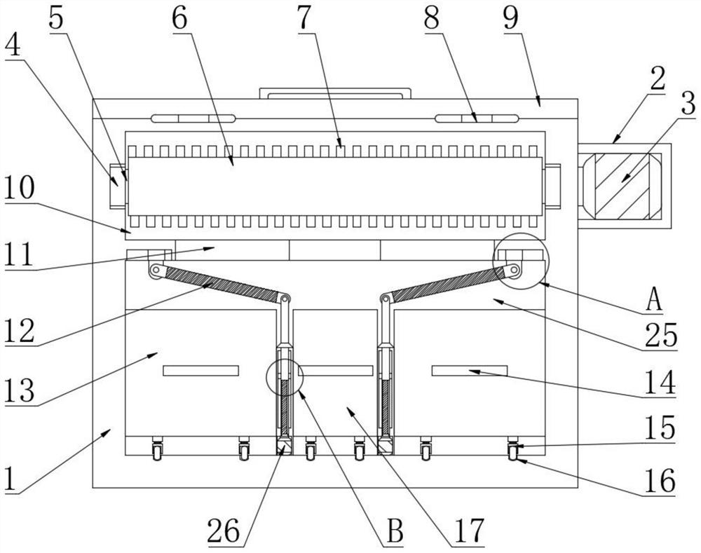
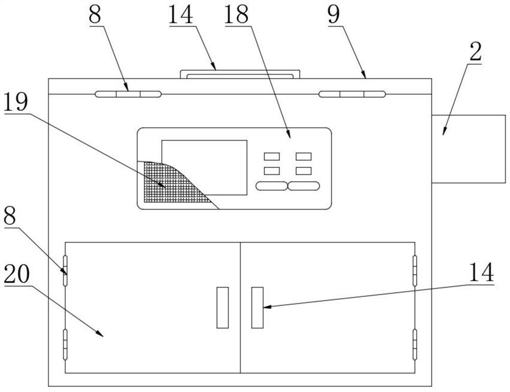
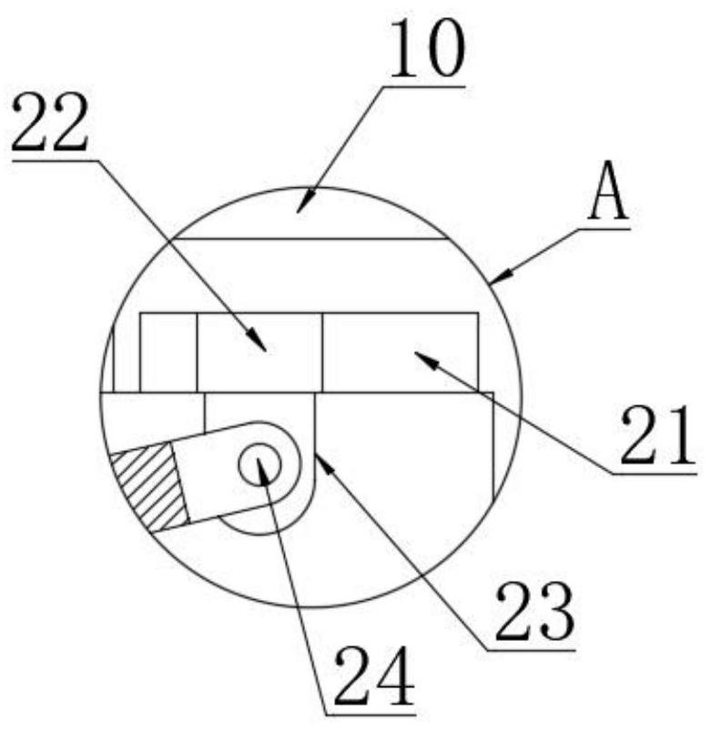
[0024] see Figure 1-6 , the present invention provides the following technical solutions: a building engineering waste treatment equipment, including a box body 1, a crushing chamber 10 and a collection chamber 25 are opened inside the box body 1, and four bearings 4 are inlaid on the inner wall of the crushing chamber 10 , the bearing 4 is pierced with a rotating shaft 5, the surface of the rotating shaft 5 is fixedly connected with a drum 6, the surface of the drum 6 and the inner wall of the crushing chamber 10 are fixedly connected with crushing teeth 7, the right side of the box 1 The outer surface is fixedly connected with a fixed frame 2, and the fixed frame 2 is fixedly connected with a first motor 3. By setting the first motor 3, the drum 6 and the crushing teeth 7 can be driven to rotate through the rotating shaft 5. At the same time, the two drums 6 and The rubbish is crushed under the interaction of the crushing teeth 7, which is convenient for users to crush rubb...


PUM


Abstract

The invention belongs to the technical field of engineering of buildings, and particularly relates to engineering garbage treatment equipment for a building. The engineering garbage treatment equipment comprises a box body, wherein a crushing room and a collecting room are arranged inside the box body; the inner wall of the crushing room is embedded with four bearings; rotary shafts are arranged in the bearings in a penetrating mode; the surfaces of the rotary shafts are fixedly connected to rollers; the surfaces of the rollers and the inner wall of the crushing room are fixedly connected to crushing teeth; and the outer surface of the right side of the box body is fixedly connected to a fixed frame. According to the engineering garbage treatment equipment for the building disclosed by theinvention, a first motor can drive the rollers and the crushing teeth to rotate through the rotary shafts; under mutual action of the two rollers and the crushing teeth, garbage is crushed, so that auser crushes garbage of different forms conveniently; a filter plate can be arranged for filtering the crushed garbage, and also can be used for sorting the crushed garbage conveniently, so that a fixed object is separated from liquid; and the structures are mutually matched, so that the integral use effect is better.

Description

technical field [0001] The invention belongs to the technical field of construction engineering, and in particular relates to construction engineering waste treatment equipment. Background technique [0002] With the acceleration of urbanization, the construction industry has also developed rapidly. However, in the process of construction, a large amount of construction waste will be generated. These construction wastes are difficult to degrade by themselves, and if they are landfilled, they will pollute Land, so that the land can only be abandoned for a long time, causing great pollution to the environment, and currently there is no device for processing construction waste on the market, so that construction waste cannot be effectively treated, and excessively large waste cannot be treated. At the same time, the treated garbage cannot be sorted, and many garbage contains moisture, which is not convenient for later personnel to process the garbage. Therefore, in view of the ...

Claims


Application Information

Patent Timeline
IPC IPC(8): B02C4/08B02C4/28B02C23/16
CPCB02C4/08B02C4/28B02C23/16B02C2023/165B02C2201/06
Inventor 不公告发明人
Owner 深圳市兰锋科技有限公司
Learn More