Rotor Slot Liner Bending Tool for Wet Winding Motors

A motor rotor and winding technology, applied in the field of wet winding motor rotor slot lining bending tools, can solve the problems of copper strip deformation, increased cost, loss of protective effect of copper strip, etc., and achieves the effect of improving efficiency and saving time and cost

Active Publication Date: 2022-04-05
HARBIN ELECTRIC POWER EQUIP
View PDF9 Cites 0 Cited by
  • Summary
  • Abstract
  • Description
  • Claims
  • Application Information

AI Technical Summary

Problems solved by technology

[0003] The slot lining of wet winding motor rotor is 0.20mm rust-free steel belt, which has a certain hardness. At first, the slot lining is bent by placing the copper strip directly on the slot lining, and using a simple insulating plate and a copper hammer to carry out the copper strip as a sample. Bending, because there is no positioning, the copper strip moves during the bending process, the slot lining cannot be fitted, the surface of the slot lining is knocked uneven, and even the paint film on the copper strip surface falls off. In severe cases, the copper strip is deformed and cannot be smoothly installed. Put the copper bar covered with the slot liner into the rotor core slot. Even if it is forced into the rotor core slot, the slot liner is easy to wrinkle or be damaged, and the copper bar will lose its protective effect.
Therefore, the traditional way of wrapping the slot liner and copper strip is not only time-consuming and laborious, but also increases a lot of cost if the slot liner is damaged during assembly.

Method used


Image

  • Rotor Slot Liner Bending Tool for Wet Winding Motors
  • Rotor Slot Liner Bending Tool for Wet Winding Motors
  • Rotor Slot Liner Bending Tool for Wet Winding Motors

Examples


Embodiment Construction

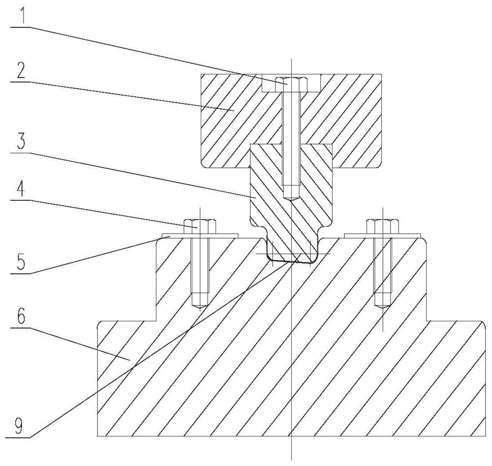
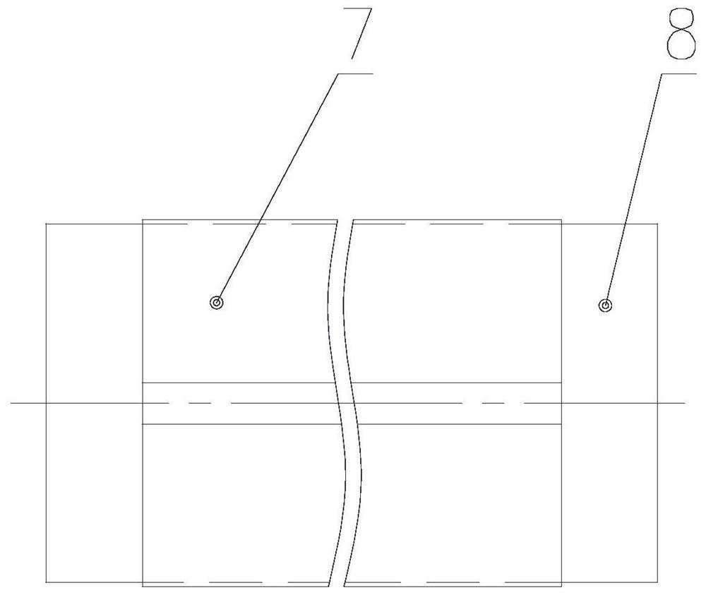
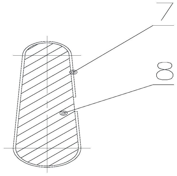
[0014] Such as figure 1 The desired wet winding motor rotor slot is thin, the tool consists of a lower mold 6, a positioning plate 5, a bolt 4, a upper mold 3, a upper mold 2, a bolt 1, and a lower mold 6 with a limit slot. 9, the positioning plate 5 is fixed to the lower mold 6, and the standard bolt 4 is fixed; the upper mold 3 is assembled with the upper mold 2, and the bolt 1 is assembled, the bolt 1 is a fully threaded bolt. The upper mold 3 is composed of a plurality of pieces, and the threaded holes are fixed on each piece; and the lower groove liner 7 is placed on the lower mold 6, and the groove liner is fixed by adjusting the positioning plate 5. Good, the coated copper strip 8 is placed on the slot, and the limit slot 9 of the lower mold 6 is correct, and the mounted upper mold 3 and the copper strip 8 are correct, by tightening multiple bolts. 1. Press the copper strip 8 into the groove lining 7 to achieve a seamless bonding of the groove liner 7 and the copper strip 8...


PUM


Abstract

The present invention designs a rotor slot lining bending tool for wet winding motors. Put the rotor slot lining on the lower mold of the bending tool, fix the slot lining on the lower mold groove by adjusting the positioning plate on the lower mold, and place the rotor Put the copper bar on the rotor slot liner and coincide with the positioning groove on the lower die at the same time, install the upper die handle on the upper die with screws, press the copper bar and the slot liner into the lower die slot at the same time, so that the outer surface of the copper bar One side is fully attached to the slot liner, the upper mold is removed, and the outer slot liner is attached to the copper strip. The shape of the slot liner of the present invention has no wrinkles and deformations, and the copper strips covered with the slot liner can be smoothly loaded into the rotor core slots. The slot shape of the lower mold of the tool is designed according to the shape of the copper strips. After assembly, the slot liner and copper strips can Seamless fit, and finally achieve the effect of protecting the copper strip.

Description

Technical field: [0001] The present invention relates to a wet winding motor rotor tank liner and curved tool. Background technique: [0002] The wet winding motor is a static seal connection in the pump portion, and the motor is co-affected by the same water pressure in the working state. The motor is filled with water, and the rotor with copper strips has long been immersed in the water. In order to prevent the copper strip from causing serious corrosion in the water in the water, The outer surface of the copper strip is painted and an outsourced lining, the rotor core is a pear slot, and the length is generally 700 ~ 1500 mm. [0003] The wet winding group motor rotor slot is 0.20 mm pharmaceous strip, there is a certain hardness, and the initial tank is curved, and the copper strip is placed directly on the groove liner, using a simple insulating plate and the copper hammer to be copper into a sample. Bending, since there is no positioning, the copper strips are moved during ...

Claims


Application Information

Patent Timeline
Patent Type & Authority Patents(China)
IPC IPC(8): B21D37/10H02K15/00H02K15/04
CPCB21D37/10H02K15/00H02K15/04H02K15/0414
Inventor 杨凤君王勇张尧周锋廷黄秀波王志威赵环宇郑维刘宇晨刘继东高明缙王策吴嘉兴
Owner HARBIN ELECTRIC POWER EQUIP
Why Eureka
Try Eureka