
Robot loading and unloading operation method based on vision positioning

A robot and robot hand technology, applied in manipulators, program-controlled manipulators, manufacturing tools, etc., can solve the problems of affecting work rhythm, photographing occlusion, and high cost, reducing tooling and labor costs, improving equipment operating rhythm, and improving productivity. Effect

Active Publication Date: 2021-12-07
SIASUN CO LTD
View PDF6 Cites 0 Cited by
  • Summary
  • Abstract
  • Description
  • Claims
  • Application Information

AI Technical Summary

Problems solved by technology

The disadvantages of the first method are: it is necessary to design a high-precision pre-positioning tooling, and at the same time, it is necessary to manually place the material on the tooling, which has high cost, poor consistency, and low precision.
The disadvantage of the second method is: if the camera is at the end of the mechanical arm to take pictures, it will affect the work rhythm, and the working conditions do not allow the camera to be fixed on the shelf to take pictures, and the pictures are easily affected by other materials or devices on the material table.

Method used


Image

  • Robot loading and unloading operation method based on vision positioning
  • Robot loading and unloading operation method based on vision positioning
  • Robot loading and unloading operation method based on vision positioning

Examples


Embodiment Construction

[0030] Preferred embodiments of the present disclosure will be described in more detail below with reference to the accompanying drawings. Although preferred embodiments of the present disclosure are shown in the drawings, it should be understood that the present disclosure can be embodied in various forms and should not be limited to the embodiments set forth herein. Rather, these embodiments are provided so that this disclosure will be thorough and complete, and will fully convey the scope of the disclosure to those skilled in the art.

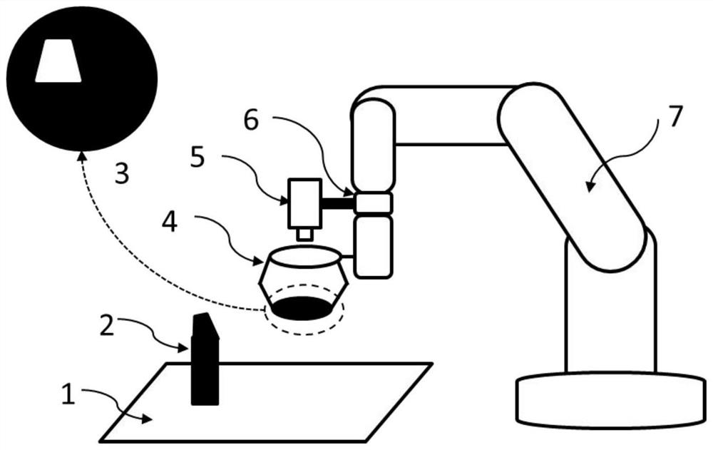
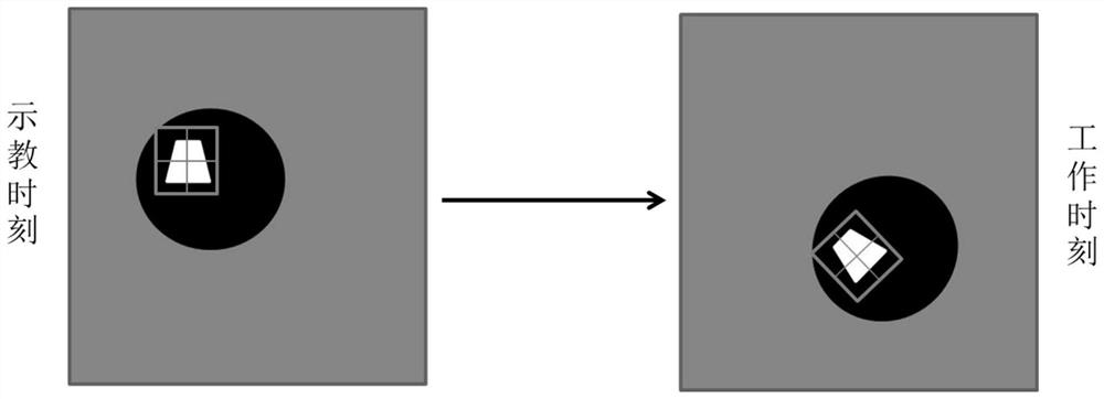
[0031] as attached figure 1 As shown, it is an exemplary embodiment of the present invention to load and unload the core parts of the automobile recliner on the welding table according to a fixed posture.

[0032] The specific requirement is to insert the positioning hole of the core part into the positioning pin of the welding table, that is, the blanking pin. Among them, the section of the positioning hole and the blanking pin of the cor...


PUM


Abstract

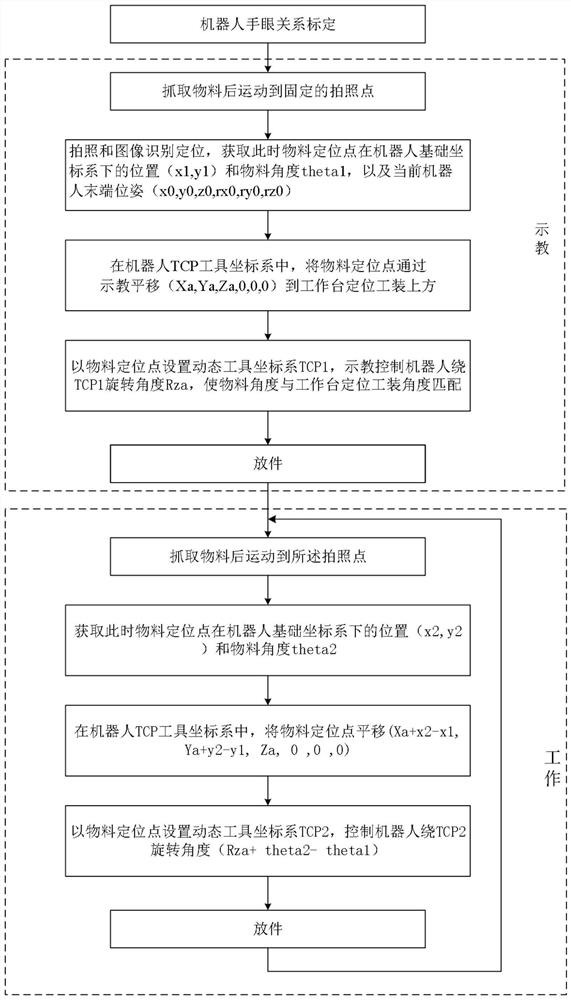
A robot loading and unloading operation method based on visual positioning, which adopts the method of grabbing the material and then taking pictures, through image recognition and positioning, to obtain the position and angle of the material positioning point, and the pose and posture of the robot flange surface at the beginning of teaching. , as a reference, and then in actual work, fine-tune the position and angle of the material compared with the reference, and finally align the position and angle of the material with the positioning tool on the workbench, so that the material can be accurately placed on the on the workbench. This method has the advantages of reducing tooling and labor costs, solving the problem that the workpiece cannot be visually positioned in the incoming material area, enabling high-precision positioning and improving production tempo, etc., and is especially suitable for material grabbing tasks in the automotive and 3C industries.

Description

technical field [0001] The invention relates to the field of visual guidance and positioning of robots, in particular to a method for loading and unloading operations of robots based on visual positioning. Background technique [0002] The application of robot vision-guided positioning in material picking and placement is becoming more and more important. In the high-precision loading and unloading operation of the existing robot, not only the material needs to be placed on the positioning tool on the workbench, but also the placement angle needs to match the structure of the positioning tool on the workbench. Among them, the positioning tool may not only limit and position the material from the periphery, but also position it from the inside of the material through positioning holes, pins, and grooves. No matter what kind, there will be a positioning center corresponding to the positioning tool on the material, and the two positions are aligned, and the placement angle of ...

Claims


Application Information

Patent Timeline
Patent Type & Authority Patents(China)
IPC IPC(8): B25J9/00B25J9/16G01C11/02
CPCB25J9/0081B25J9/161B25J9/1612B25J9/1661B25J9/1697G01C11/02
Inventor 杨跞朱小生刘一帆左方睿许楠李法设
Owner SIASUN CO LTD
Learn More