
Electric rotary clamp for rock cutting machine

An electric rotary cutting machine technology, applied in the field of machinery, can solve the problems of fixed end offset, poor end surface flatness, and inconsistent design dimensions, etc., to ensure flatness and integrity, improve cutting efficiency, and reasonable device cost Effect

Pending Publication Date: 2020-09-08
TIANJIN UNIV
View PDF1 Cites 3 Cited by
  • Summary
  • Abstract
  • Description
  • Claims
  • Application Information

AI Technical Summary

Problems solved by technology

The rock cutting machine itself is not equipped with a special fixed sample fixture. It is necessary to choose different clamping methods reasonably according to the shape and size of the sample and fix the sample firmly. Otherwise, the cutting quality will not be guaranteed, and even safety problems will be caused.
[0003] The clamps used in the current rock cutting process mainly include V-shaped slotted rock sample clamps. Although this type of clamp is widely used to fix samples of different sizes, the fixed end will be offset at a certain angle during the cutting process; and due to The rock cutting blade is cut from one side, the force on the sample is not uniform, and the cut sample is easy to collapse and the quality is poor
In addition, before cutting a sample of a specified size, it is necessary to manually measure the size of the original sample and mark it with a line. waste
A rock cutter sample fixture (Patent No.: CN110208057A) designed on this basis adds an L-shaped scale to the outside of the positioning frame, which can conveniently and accurately view and adjust the cutting length, but because it is still fixed on one side Sample, the flatness of the end face of the sample after cutting is not good, and the cutting quality is poor

Method used


Image

  • Electric rotary clamp for rock cutting machine
  • Electric rotary clamp for rock cutting machine
  • Electric rotary clamp for rock cutting machine

Examples


Embodiment Construction

[0031] The present invention will be described in detail below in conjunction with specific embodiments. The following examples will help those skilled in the art to further understand the present invention, but do not limit the present invention in any form. It should be noted that those skilled in the art can make several modifications and improvements without departing from the concept of the present invention. These all belong to the protection scope of the present invention.

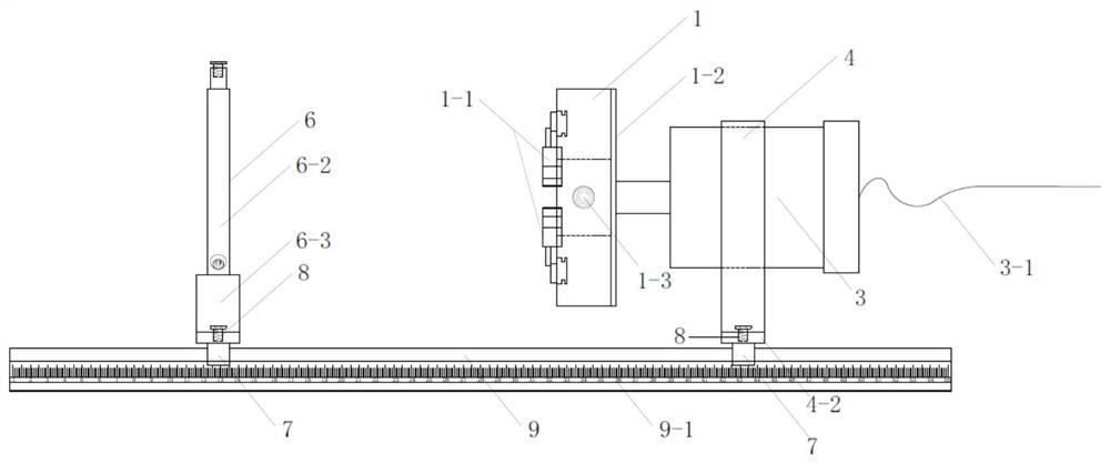
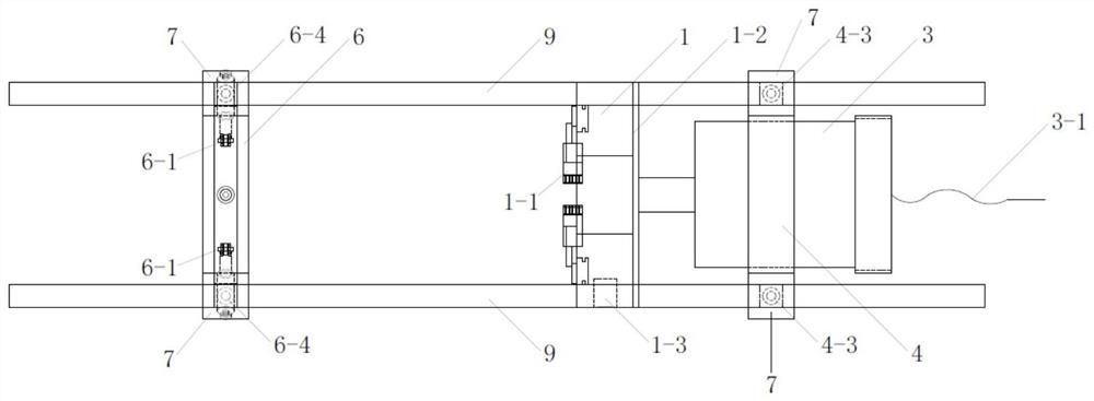
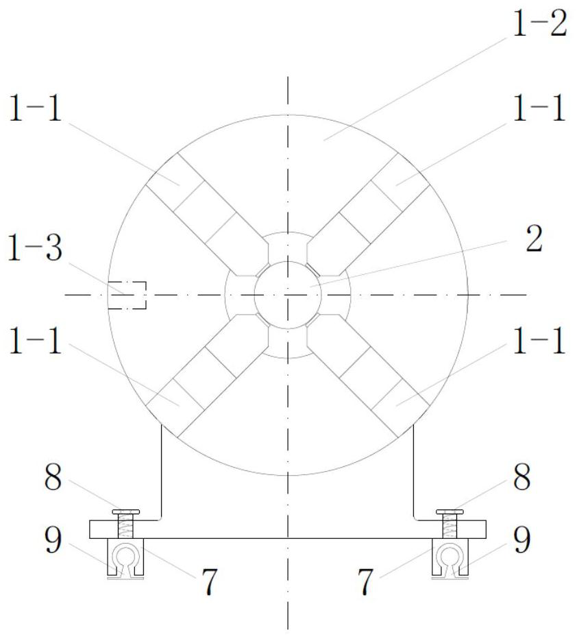
[0032] Such as Figure 1-Figure 6 As shown, an electric rotary fixture for a rock cutter according to an embodiment of the present invention includes a guide rail 9, a special-shaped frame 4 mounted on the guide rail 9 through a linear bearing slider 7 and a roller center frame 6, and a special-shaped frame 4 mounted on the special-shaped frame 4 The rock cutter 5 between the roller center frame 6 and the four-jaw self-centering chuck 1 installed on the special-shaped frame 4, the end of the four-...


PUM

PropertyMeasurementUnit
Thicknessaaaaaaaaaa
Outer diameteraaaaaaaaaa
Heightaaaaaaaaaa

Abstract

The invention relates to the technical field of machinery, and particularly relates to an electric rotary clamp for a rock cutting machine. The electric rotary clamp comprises a guide rail, a special-shaped frame, a roller center frame, the rock cutting machine and a four-claw self-centering chuck, wherein the special-shaped frame and the roller center frame are mounted on the guide rail through linear bearing sliding blocks, the rock cutting machine is mounted between the special-shaped frame and the roller center frame, and the four-claw self-centering chuck is mounted on the special-shapedframe. The tail end of the four-claw self-centering chuck is connected with the driving end of a motor horizontally embedded in the special-shaped frame through a bearing, and the motor drives the four-claw self-centering chuck to rotate around the axis to drive a rock sample to rotate around the axis; and the four-claw self-centering chuck and the roller center frame firmly fix the two ends of the cylindrical rock sample, the cylindrical rock sample is horizontally arranged above a cutting table of the rock cutting machine, and a circular blade of the rock cutting machine is perpendicular tothe cylindrical rock sample. According to the electric rotary clamp, the cylindrical sample can continuously rotate around the axis in the rock cutting process, and the cutting position can be quicklyand accurately determined.

Description

technical field [0001] The invention relates to the technical field of machinery, in particular to an electric rotary clamp for a rock cutter. Background technique [0002] In the related tests of rock and concrete, it is often necessary to cut the cylindrical sample along the radial direction according to the test requirements. At present, the rock cutting machine is mainly used to realize it. The rock cutting machine itself is not equipped with a special fixed sample fixture. It is necessary to choose different clamping methods reasonably according to the shape and size of the sample and fix the sample firmly. Otherwise, the cutting quality will not be guaranteed and may even cause safety problems. [0003] The clamps used in the current rock cutting process mainly include V-shaped slotted rock sample clamps. Although this type of clamp is widely used to fix samples of different sizes, the fixed end will be offset at a certain angle during the cutting process; and due to ...

Claims


Application Information

Patent Timeline
IPC IPC(8): B28D1/24B28D7/04B28D7/00G01N1/28
CPCB28D1/24B28D7/00B28D7/04G01N1/286G01N2001/2873
Inventor 夏开文王帅江丽媛吴帮标余裕超
Owner TIANJIN UNIV
Learn More