A transmission method based on belt conveying

A belt conveying and driving wheel technology, applied in conveyors, electric components, transportation and packaging, etc., can solve the problems of waste of resources, increase capital investment, unfavorable production, etc., achieve good control, reduce start-up difficulty, and large friction force effect

Active Publication Date: 2022-01-14
佛山市科尼明五金制品有限公司
View PDF6 Cites 0 Cited by
  • Summary
  • Abstract
  • Description
  • Claims
  • Application Information

AI Technical Summary

Problems solved by technology

[0002] When the belt conveyor in the prior art is started, it usually needs a conveyor belt with a long load to start, that is, to start with a load, but the motor generally cannot provide a large driving force during the start-up stage, and the existing one The solution is to choose a large-load motor, that is, use a motor that exceeds the carrying capacity of the belt conveyor to provide the driving force in the start-up phase, which causes waste of resources and increases capital investment, which is not conducive to production

Method used


Image

  • A transmission method based on belt conveying
  • A transmission method based on belt conveying
  • A transmission method based on belt conveying

Examples


Embodiment 1

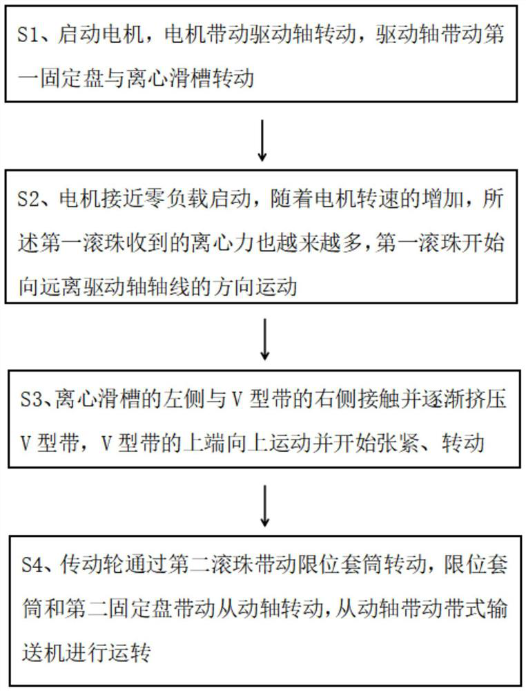
[0030] Such as figure 1 Described, a kind of transmission method based on belt conveying, this transmission method comprises the following steps:

[0031] S1, start the motor, the motor drives the drive shaft 14 to rotate, and the drive shaft 14 drives the first fixed disk 7 and the centrifugal chute 10 to rotate, because there is a large distance between the first fixed disk 7 and the centrifugal chute 1, so it cannot drive The V-belt 1 rotates, so the motor does not drive the belt conveyor to run at this moment.

[0032] S2. The motor is started with close to zero load. As the motor speed increases, the first ball 11 receives more and more centrifugal force, and the first ball 11 starts to move away from the axis of the drive shaft 14, and squeezes the centrifugal force. On the right side of the chute 10, the centrifugal chute 10 overcomes the elastic force of the first spring 9 and moves to the left.

[0033] S3. The left side of the centrifugal chute 10 is in contact wit...

Embodiment 2

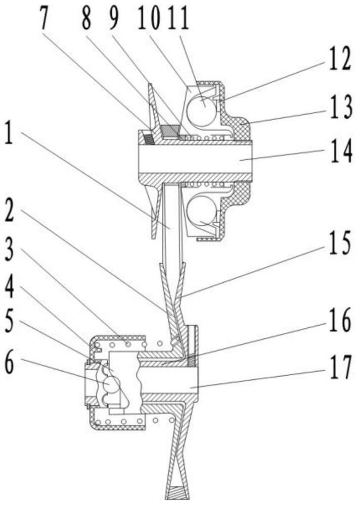
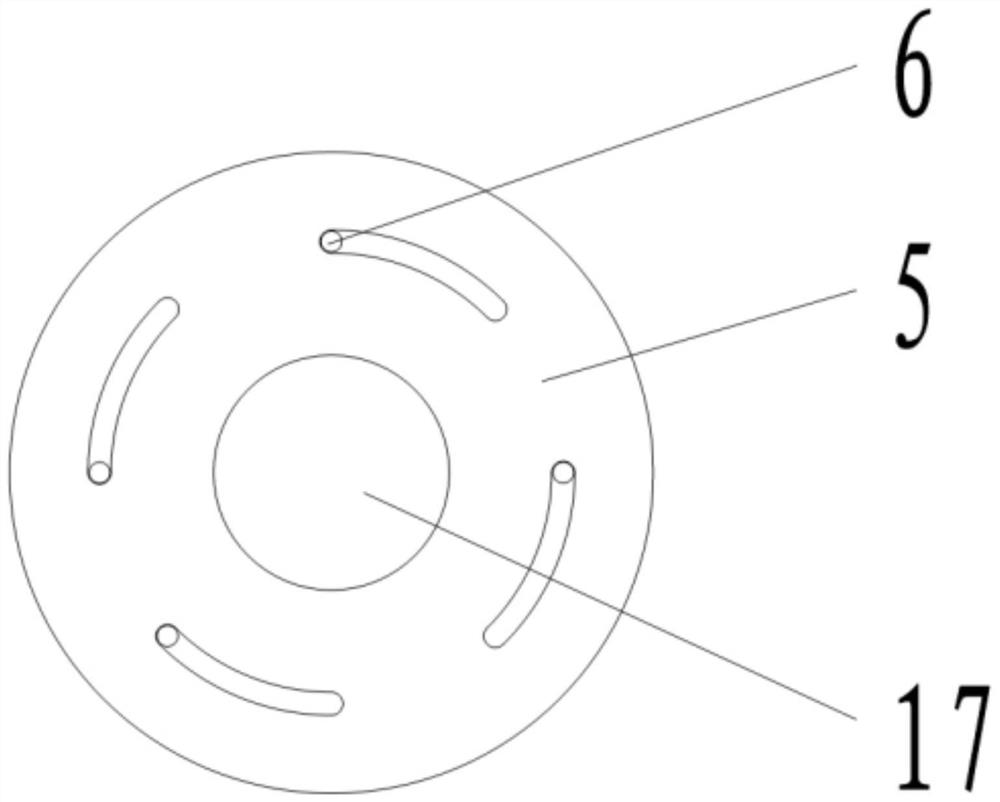
[0044] Such as figure 2 , 4 As shown in -5, a transmission mechanism for a belt conveyor includes: a drive shaft 14, used to drive the V-belt 1, and then drives a driven shaft 17, and the driven shaft 17 is used to drive the belt conveyor The transmission mechanism is used to transmit the driving force of the drive shaft 14 to the driven shaft 14 when the drive shaft 14 reaches a certain speed.

[0045] The transmission mechanism includes a driving end transmission mechanism and a driven end transmission mechanism, the driving end transmission mechanism is used to gradually tension the V-belt 1 when the drive shaft 14 reaches a certain speed, and the driven end transmission mechanism is used for The V-belt 1 that is gradually tensioned is connected with the driven shaft 17 in transmission. During the process of the V-belt 1 being gradually tensioned, the drive shaft 14 and the driven shaft 17 have a gradually smaller transmission ratio.

[0046] The driving end transmissio...


PUM


Abstract

The invention relates to a transmission method based on belt conveying. The transmission method includes the following steps: S1, start the motor, the motor drives the drive shaft to rotate, and the drive shaft drives the first fixed disk and the centrifugal chute to rotate; S2, the motor is close to zero load Start, as the motor speed increases, the first ball receives more and more centrifugal force, and the first ball starts to move away from the axis of the drive shaft; S3, the left side of the centrifugal chute and the V-shaped belt The right side contacts and gradually squeezes the V-shaped belt, the upper end of the V-shaped belt moves upwards and starts to be tensioned and rotated; S4, the transmission wheel drives the limit sleeve to rotate through the second ball, and the limit sleeve and the second fixed plate drive The driven shaft rotates, and the driven shaft drives the belt conveyor to run.

Description

technical field [0001] The invention relates to the technical field of belt conveyors, in particular to a transmission method based on belt conveyors. Background technique [0002] When the belt conveyor in the prior art is started, it usually needs a conveyor belt with a long load to start, that is, to start with a load, but the motor generally cannot provide a large driving force during the start-up stage, and the existing one The solution is to choose a large-load motor, that is, use a motor that exceeds part of the carrying capacity of the belt conveyor to provide the driving force in the start-up phase, which causes waste of resources and increases capital investment, which is not conducive to production. [0003] Based on the technical problems existing in the prior art, the present invention provides a transmission method based on a belt conveyor. Contents of the invention [0004] The purpose of the present invention is to address the above problems, to provide a ...

Claims


Application Information

Patent Timeline
Patent Type & Authority Patents(China)
IPC IPC(8): B65G23/22B65G23/24B65G23/44H02K7/10
CPCB65G23/22B65G23/24B65G23/44H02K7/1016
Inventor 朱箫笛
Owner 佛山市科尼明五金制品有限公司
Why Eureka
Try Eureka