A snow layered turning and throwing device for reshaping and cleaning ski slopes

A flipping device and technology for ski resorts, applied in snow surface cleaning, cleaning methods, construction, etc., can solve the problems of high cost of ski slope remodeling and failure to meet the purity requirements of ski slopes, so as to realize automatic dredging and prevent blockage , to ensure the effect of uniformity

Active Publication Date: 2021-11-23
卫晓峰
View PDF12 Cites 0 Cited by
  • Summary
  • Abstract
  • Description
  • Claims
  • Application Information

AI Technical Summary

Problems solved by technology

[0008] Aiming at the deficiencies of the prior art, the present invention provides a layered snow turning and throwing device for ski slope remodeling and cleaning, which solves the problem of the high cost of ski slope remodeling and the inability of traditional turning and throwing equipment to meet the requirements of pure ski trails. Degree Requirement Questions

Method used


Image

  • A snow layered turning and throwing device for reshaping and cleaning ski slopes
  • A snow layered turning and throwing device for reshaping and cleaning ski slopes
  • A snow layered turning and throwing device for reshaping and cleaning ski slopes

Examples


Embodiment 1

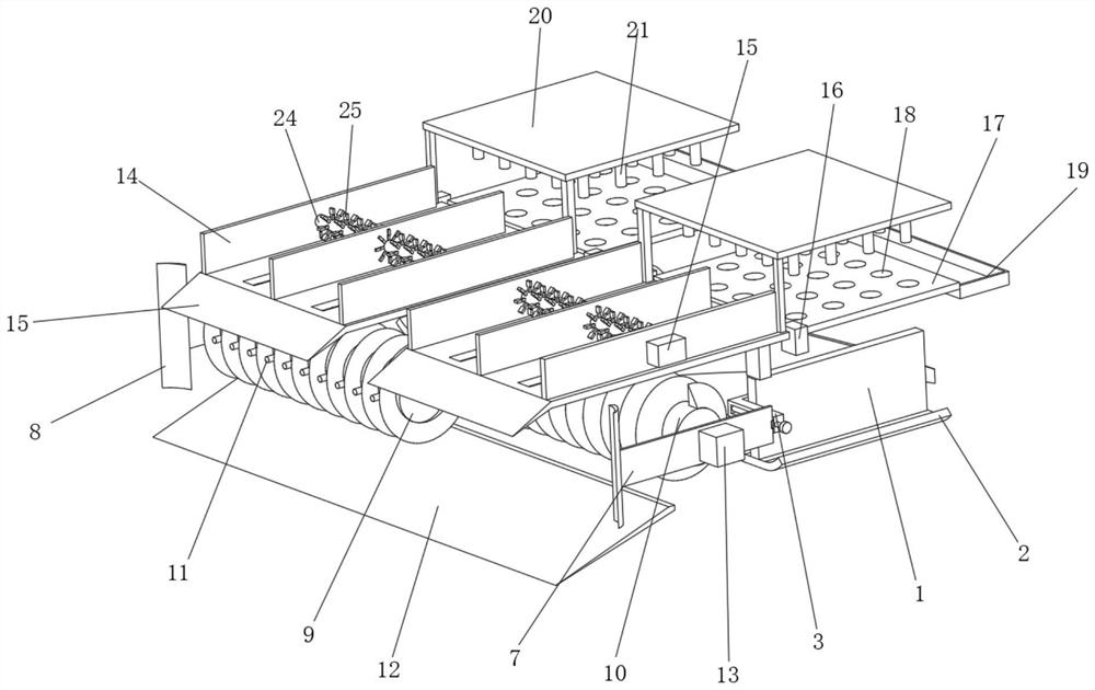
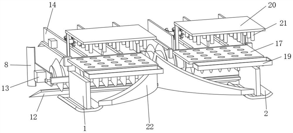
[0036] Such as Figure 1-4 As shown, the present invention provides a technical solution: a snow layer turning and throwing device for ski slope remodeling and cleaning, including a support baffle 1, the bottom of the support baffle 1 is fixedly connected with a walking slide 2, and the support baffle The front of the plate 1 is fixedly connected with an adjusting support plate 3, and the inside of the adjusting support plate 3 is fixedly connected with a limiting track 4, and the inner rotation of the limiting track 4 is connected with an adjusting threaded rod 5, and the outer surface of the adjusting threaded rod 5 is sleeved and threaded. The transmission threaded block 6 is connected, and the outside of the transmission threaded block 6 is fixedly connected with the installation side frame 7, and one end of the installation side frame 7 at the front is fixedly connected with a slideway side shovel 8, and the installation side frame 7 on the left side is close to the front ...

Embodiment 2

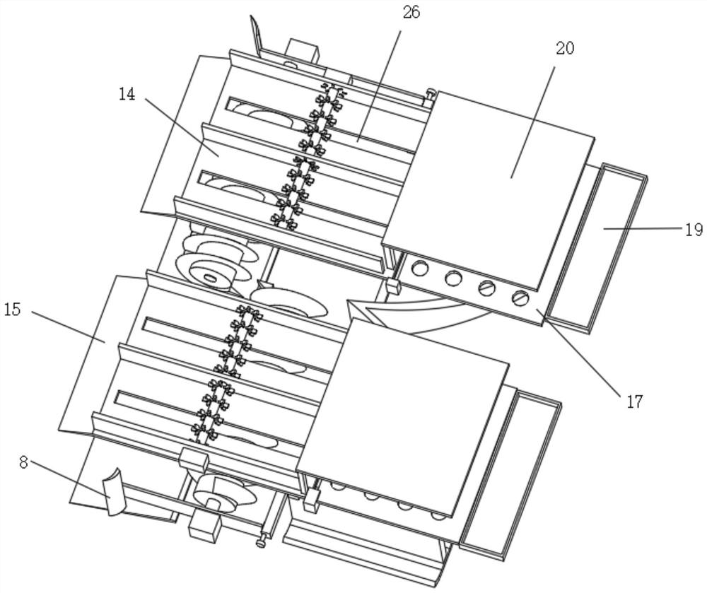
[0044] Such as Figure 5 Shown, on the basis of Embodiment 1, the present invention provides a kind of technical solution: a kind of ski resort skidway remodeling cleans up and uses snow layer to throw device, and electromagnetic drive mechanism 16 comprises drive shell 161, and the drive shell 161 One side is fixedly connected with the upper shovel rail 14, and the vertical position inside the drive housing 161 is slidably connected with a movable slider 162, and the right side of the movable slider 162 extends to the outside, and the right side of the movable slider 162 is connected to the sieve plate 17 fixed connections.

[0045] A magnet 163 is fixedly connected to the bottom of the movable slider 162 , an electromagnet 164 is fixedly connected to the inner bottom of the driving housing 161 , and an extruding spring 165 is sheathed and fixedly connected to the outside between the magnet 163 and the electromagnet 164 .

[0046] A power supply 166 is fixedly connected to t...


PUM


Abstract

The invention discloses a layered snow turning and throwing device for remodeling and cleaning ski slopes in a ski resort, which includes a support baffle, one end of the installation side frame on the front side is fixedly connected with a slide side shovel, and the installation side frame on the left side is close to the The front position is rotatably connected with a front turning throwing wheel, the side frame on the right side is installed and the position near the back is rotatably connected with a rear turning throwing wheel, the surfaces of the front turning throwing wheel and the rear turning throwing wheel are fixed with spiral blades, and the front turning throwing wheel The outer surface of the wheel and the rear turning and throwing wheel and the position between the spiral blades are fixedly connected with turning bumps, the lower part of the front side frame is fixedly connected with a shoveling inclined knife plate, and the front side of the upper shoveling track is fixedly connected with an upper The shoveling sloping plate is fixedly connected with a sieving plate through an electromagnetic drive mechanism on the back of the shoveling sloping plate. The invention relates to the technical field of ski resorts. The snow layering and throwing device used for cleaning and reshaping ski slopes in the ski resort achieves targeted layering treatment of ski slopes and improves the purity of the ski slope remodeling.

Description

technical field [0001] The invention relates to the technical field of ski resorts, in particular to a snow layer turning and throwing device for reshaping and cleaning slideways in ski resorts. Background technique [0002] Skiing is a competitive sport in which athletes put skis on the soles of their boots to perform speed, jump and downhill on the snow. Snowboards are made from a mix of wood, metal and plastic. Alpine skiing consists of downhill, slalom and slalom. [0003] For example, the Chinese invention publication number is: CN107923134A, a hydraulic device for supplying a track setting device for producing cross-country ski tracks; the device (3) includes: a first inlet (6), for receiving fluid; a first Outlet (7) and second outlet (8) for releasing two fluid streams; first hydraulically coupled motor (9) with second inlet (10), third outlet (11) and first shaft (12) and a second hydraulically coupled motor (13) with a third inlet (14), a fourth outlet (15) and ...

Claims


Application Information

Patent Timeline
Patent Type & Authority Patents(China)
IPC IPC(8): E01H4/02
CPCE01H4/02
Inventor 王念卫晓峰
Owner 卫晓峰
Why Eureka
Try Eureka