Coal mine underground complex stratum directional drilling pressure control drilling system

A complex formation, directional drilling technology, applied in directional drilling, drilling tools, drilling equipment, etc., can solve problems such as reducing the effect of flushing fluid, and achieve the effects of improving stability, increasing pressurization effect, and reducing the possibility of collapse

Active Publication Date: 2020-09-08
HENAN POLYTECHNIC UNIV
View PDF5 Cites 1 Cited by
  • Summary
  • Abstract
  • Description
  • Claims
  • Application Information

AI Technical Summary

Problems solved by technology

[0003] In the process of directional drilling, the drill pipe is used to drive the drill bit to rotate. There is a central hole in the drill pipe. The central hole is connected to the external faucet. The flushing fluid is injected into the central hole through the faucet. When the drill bit enters the borehole, an annular space is formed between the drill hole and the drill pipe. The flushing fluid passes through the annular space to take out impurities such as rock slag, and the flushing fluid can also reduce the temperature of the drill bit and improve the drilling effect. However, due to the lack of pressure control of the mixed liquid in the annular space in the existing devices, or the relatively simple means of pressure control, it is difficult for the flushing liquid to form a supporting filter membrane on the hole wall, which greatly reduces the effect of the flushing liquid

Method used


Image

  • Coal mine underground complex stratum directional drilling pressure control drilling system
  • Coal mine underground complex stratum directional drilling pressure control drilling system
  • Coal mine underground complex stratum directional drilling pressure control drilling system

Examples


Embodiment Construction

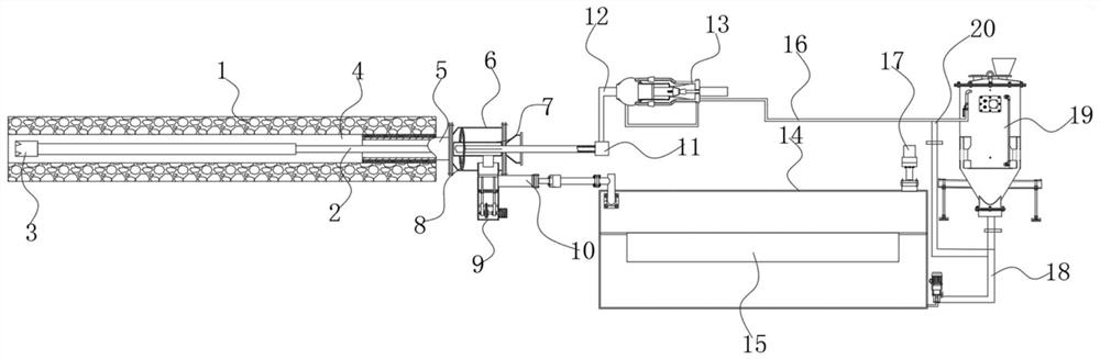
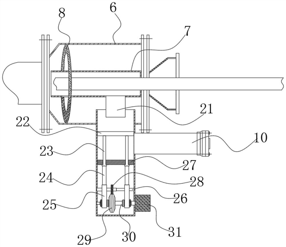
[0026] see Figure 1~3 , in an embodiment of the present invention, a directional drilling and pressure-controlled drilling system for complex underground coal mine formations, which includes a drill pipe 2, a sealing tube 5, a water release chamber 6, a hydraulic pressure control assembly and a hydraulic pressure control assembly 13, Wherein, the drill pipe 2 extends into the borehole 1 and forms an annulus 4 with the borehole 1, and a sealing pipe 5 is fixedly embedded at the entrance of the borehole 1, so that the mixed liquid in the annulus 4 flows through Seal tube 5 to the outside,

[0027] Wherein, the sealing pipe 5 is connected with the water release chamber 6 by a flange, and the bottom of the water discharge chamber 6 is connected with the liquid outlet pressure control assembly, and the liquid outlet control pressure assembly can adjust the seal of the liquid outlet. Blockage area, so as to control the liquid outlet pressure of the mixed liquid in the annular spac...


PUM


Abstract

The invention discloses a coal mine underground complex stratum directional drilling pressure control drilling system. The system involves a drill rod, a sealing pipe, a water release bin, a liquid outlet pressure control assembly and a liquid inlet pressure control assembly, wherein the drill rod stretches into a drill hole, an annulus is formed between the drill rod and the drill hole, the sealing pipe is fixedly embedded into an inlet of the drill hole so that mixed liquid in the annulus can flow to outside through the sealing pipe, the sealing pipe is connected with the water release bin through a flange, the bottom of the water release bin is connected with the liquid outlet pressure control assembly, and the liquid outlet pressure control assembly can adjust the plugging area of a liquid outlet so that the liquid outlet pressure of the mixed liquid in the annulus can be controlled. According to the system, the end, away from the drill hole, of the drill rod sequentially penetrates through the sealing pipe and the water release bin so as to enable a center hole in the drill rod to be connected with a faucet, the other end of the faucet is connected with the liquid inlet pressure control assembly, and the liquid inlet pressure control assembly can conduct pressurization pressure control in a pulse mode while continuously feeding liquid to the center hole in the drill rod, so that the bidirectional pressure control is realized.

Description

technical field [0001] The invention belongs to the technical field of trash can disinfection, in particular to a pressure-controlled drilling system for directional drilling in complex strata in underground coal mines. Background technique [0002] In the process of underground coal mining, the problem of gas outburst is often encountered, especially in complex strata. Gas disasters seriously threaten the safe production of coal mines. The gas in the hole is pre-drained, so as to reduce the gas content in the coal seam and reduce the occurrence of such accidents. [0003] In the process of directional drilling, the drill pipe is used to drive the drill bit to rotate. There is a central hole in the drill pipe. The central hole is connected to the external faucet. The flushing fluid is injected into the central hole through the faucet. When the drill bit enters the borehole, an annular space is formed between the drill hole and the drill pipe. The flushing fluid passes throu...

Claims


Application Information

Patent Timeline
Patent Type & Authority Applications(China)
IPC IPC(8): E21B7/04E21B21/00E21B12/00
CPCE21B7/04E21B21/00E21B12/00
Inventor 王蔚王筱超彭磊郭明功张法政冯文涛王岳栩李彦志王恩杜鲁占陈旭贾海林刘彦伟高保彬王文
Owner HENAN POLYTECHNIC UNIV
Why Eureka
Try Eureka