Manufacturing method of forced centering bracket for existing pre-buried slide groove and T-shaped bolts

A technology of forced centering and manufacturing method, applied in the field of shield tunnel measurement, can solve the problems of long operation time of mounting bracket, low cycle utilization rate of the bracket, inconvenient carrying of the bracket, etc., saving manpower and installation time. , The effect of simple and convenient installation and operation

Inactive Publication Date: 2020-09-08
CHINA COMM 2ND NAVIGATIONAL BUREAU 3RD ENG
View PDF18 Cites 0 Cited by
  • Summary
  • Abstract
  • Description
  • Claims
  • Application Information

AI Technical Summary

Problems solved by technology

[0004] Aiming at the problems that the bracket is inconvenient to carry, the working time for installing the bracket is long, the bracket is damaged and deformed, the recycling rate is low, and the segments need to be repaired after the bracket is disassembled, the invention proposes an existing pre-buried chute and a T-shaped The manufacturing method of the forced centering bracket of bolts transforms the existing forced centering bracket into a non-drilling installation mode, which effectively ensures the excavation speed of the shield tunnel and saves manpower, material resources and operating time

Method used


Image

  • Manufacturing method of forced centering bracket for existing pre-buried slide groove and T-shaped bolts
  • Manufacturing method of forced centering bracket for existing pre-buried slide groove and T-shaped bolts
  • Manufacturing method of forced centering bracket for existing pre-buried slide groove and T-shaped bolts

Examples


specific Embodiment approach 1

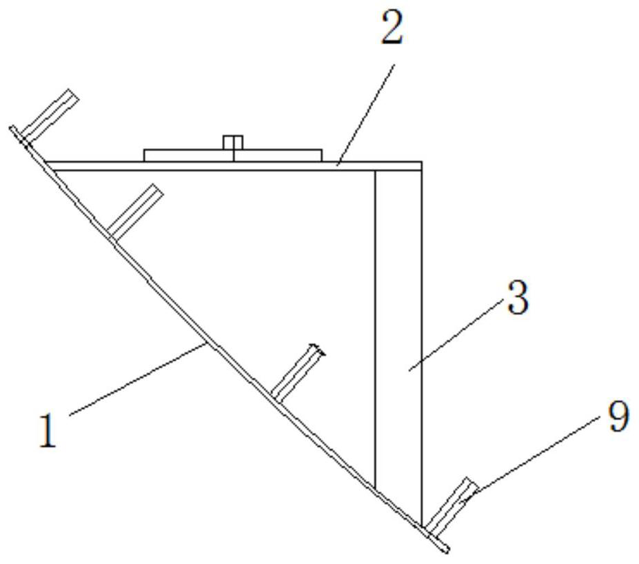
[0053] Specific implementation mode one: see Figure 1-Figure 3 This embodiment will be described. A method for manufacturing a forced centering bracket with pre-embedded chute and T-shaped bolts described in this embodiment specifically includes the following steps:

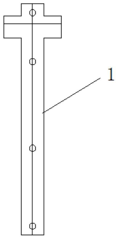
[0054] (1) Make No. 1 arc-shaped steel plate 1 installed on the pre-embedded chute of the segment, and the No. 1 arc-shaped steel plate 1 is fixed on the existing pre-embedded chute inside the segment by T-bolt 9, so The No. 1 arc-shaped steel plate 1 is provided with several circular holes corresponding to the positions of the existing embedded chute, and is used for passing through the T-shaped bolts 9;

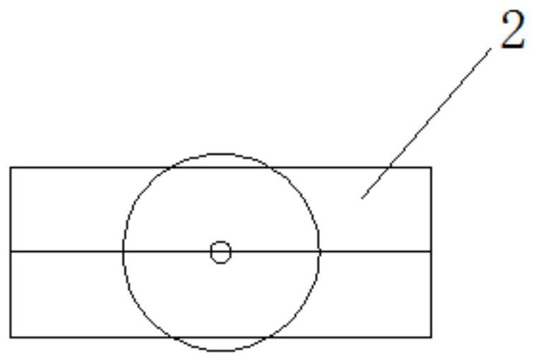
[0055] (2) make and place No. 1 square steel plate 2 of forced centering dish, described No. 1 square steel plate 2 is installed on the top of the head end of No. 1 curved steel plate 1;

[0056] (3) making No. 1 angle steel 3 that is connected with No. 1 curved steel plate and No. 1 square steel plate resp...

specific Embodiment approach 2

[0064] Specific implementation mode two: see Figure 4-Figure 5 This embodiment will be described. A method for manufacturing a forced centering bracket with pre-embedded chute and T-shaped bolts described in this embodiment specifically includes the following steps:

[0065] (1) Make No. 1 arc-shaped steel plate 1 installed on the pre-embedded chute of the segment, and the No. 1 arc-shaped steel plate 1 is fixed on the existing pre-embedded chute inside the segment by T-bolt 9, so The No. 1 arc-shaped steel plate 1 is provided with several circular holes corresponding to the positions of the existing embedded chute, and is used for passing through the T-shaped bolts 9;

[0066] (2) make and place No. two square steel plates 4 of forced centering dish, described No. two square steel plates 4 are installed on the top of the head end of No. one curved steel plate 1;

[0067] (3) making No. 2 angle steel 5 that is connected with No. 1 curved steel plate and No. 2 square steel p...

specific Embodiment approach 3

[0072] Specific implementation mode three: see Figure 6-Figure 8 This embodiment will be described. A method for manufacturing a forced centering bracket with pre-embedded chute and T-shaped bolts described in this embodiment specifically includes the following steps:

[0073] (1) Make two No. 2 arc-shaped steel plates 6 installed on the segment pre-embedded chute, each arc-shaped steel plate 6 is provided with a circular hole;

[0074] (2) make No. 3 square steel plates 7 that place the forced centering dish, and described No. 3 square steel plates 7 are positioned at the below of two No. 2 curved steel plates 6;

[0075] (3) make two square steel pipes 8 that are connected with No. two curved steel plates 6 and No. three square steel plates 7 respectively, and two square steel tubes 8 are perpendicular to No. three square steel plates 7;

[0076] (4) The lower ends of the two square steel pipes 8 are welded vertically to the upper right starting end of the No. 3 square st...


PUM


Abstract

The invention provides a manufacturing method of a forced centering bracket for an existing pre-buried slide groove and T-shaped bolts. The implementation method comprises the steps that an arc-shapedsteel plate installed on a segment pre-buried slide groove is manufactured at first, the arc-shaped steel plate is fixed to the existing pre-buried slide groove on the inner side of a segment throughthe T-shaped bolts, a square steel plate for placing a forced centering disc is manufactured, and then, angle steel connected with the arc-shaped steel plate and the square steel plate is manufactured; and the arc-shaped steel plate, the square steel plate and the angle steel are welded together to form a bracket, and the bracket is fixed to the existing pre-buried slide groove on the inner sideof the segment through the T-shaped bolts. The problems that a bracket is inconvenient to carry, long in installing operation time, large in damage deformation and low in recycling rate, and a segmentneeds to be repaired after the bracket is disassembled are solved. According to the manufacturing method, an existing forced centering bracket is transformed to be in a non-drilling installation mode, the tunneling speed of a shield tunnel is effectively ensured, and manpower, material resources and operation time are saved.

Description

technical field [0001] The invention specifically relates to a manufacturing method of a forced centering bracket with a pre-embedded chute and T-shaped bolts, and belongs to the technical field of shield tunneling measurement. Background technique [0002] The second phase project of Harbin Metro Line 3 is a two-line tunnel between Haping Road Station and Xusheng Street Station. The length of the left line is 1500.761m, and the length of the right line is 1494.611m. The slope of the line is "V" and the minimum flat curve radius 450, the maximum slope is 27.261‰, and the covering soil thickness is 8.5-36m. The shields on the left and right lines of the tunnel start from the small mileage end at Xusheng Street Station, and are disassembled and hoisted out when they arrive at the long mileage end at Haping Road Station. [0003] Since the shield tunneling section from Haping Road Station to Xusheng Street Station is about 1500m long, in order to ensure the accuracy of the pla...

Claims


Application Information

Patent Timeline
Patent Type & Authority Applications(China)
IPC IPC(8): E21D9/00E21D9/14E21F17/02E21F17/18E21F17/00
CPCE21D9/00E21D9/003E21D9/14E21F17/00E21F17/02E21F17/18
Inventor 孔凡荣陈龙丰冬冬冷远桂德明刘青山黄敏朱潇潇类兴珂
Owner CHINA COMM 2ND NAVIGATIONAL BUREAU 3RD ENG
Why Eureka
Try Eureka