Feeding system and roof bolter
A feeding system and silo technology, applied in the installation of bolts, drilling equipment, earthwork drilling and mining, etc., can solve the problems of safety hazards, difficult filling process, low work efficiency, etc., to avoid safety hazards and simplify filling The effect of improving the filling process and improving the filling efficiency
- Summary
- Abstract
- Description
- Claims
- Application Information
AI Technical Summary
Problems solved by technology
Method used
Image
Examples
Embodiment 1
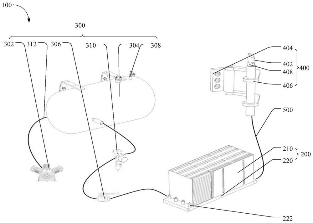
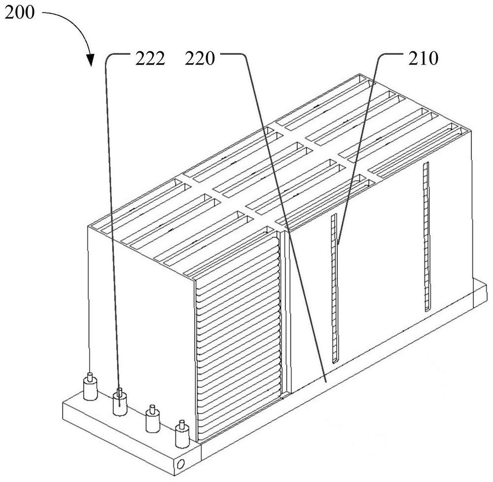
[0043] Such as figure 1 and image 3 As shown, the first aspect of the present invention provides a feeding system 100, comprising: a feed bin 200, the feed bin 200 includes: a storage bin 210; a launch bin 220, the launch bin 220 communicates with the storage bin 210; a drive assembly 300 , the driving assembly 300 is connected with the launch position 220 and is configured to drive the movement of materials in the launch position 220 ;
[0044] In the feeding system 100 provided by the present invention, firstly, the materials to be filled are placed in the silo 200, the silo 200 includes a storage bin 210 and a launch bin 220, the storage bin 210 is used to store a plurality of materials to be filled, and the launch bin 200 220 is used to place the next material to be filled, and then, the driving assembly 300 connected to the launch position 220 provides power for the material to be filled in the launch position 220, so that the material moves to the outside of the launch...
Embodiment 2
[0052] On the basis of the above examples, if figure 1 As shown, the feeding system 100 also includes a transmission pipeline 500, the two ends of the transmission pipeline 500 are respectively connected with the material outlet and the feeding gun 400, and the transmission pipeline 500 is a flexible pipeline.
[0053] In this embodiment, through the setting of the flexible transmission pipe 500, the feeding gun 400 can move freely according to different working environments, so as to complete the filling work and realize the transmission between the firing position 220 and the feeding gun 400. While being connected, the moving range of the feeding gun 400 is further increased, thereby satisfying material filling work in more working environments, and further increasing the practicability of the feeding system 100 .
[0054] Furthermore, the local minimum bending radius of the transmission pipeline 500 cannot be smaller than the allowable bending radius of the material, so as ...
Embodiment 3
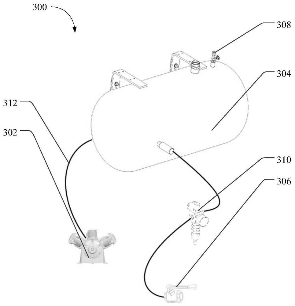
[0057] On the basis of any of the above-mentioned embodiments, such as figure 2 As shown, the drive assembly 300 includes: an air compressor 302; an air storage tank 304, the air storage tank 304 is connected to the air compressor 302 and the launch position 220 through an air pipeline 312; a stop valve 306, the stop valve 306 is arranged in the storage On the gas transmission line 312 between the gas tank 304 and the launch position 220 .
[0058] In this embodiment, the gas is compressed into the gas storage tank 304 by the air compressor 302 , and the high-pressure gas in the gas storage tank 304 is used to provide driving force for the materials to be loaded in the launch position 220 . Specifically, the gas storage tank 304 is connected with the launch position 220 through the gas pipeline 312, and a cut-off valve 306 is set between the gas storage tank 304 and the launch position 220, and the high-pressure gas is realized by notifying the cut-off valve 306. output, so ...
PUM
 Abstract
Description
Claims
Application Information
 - R&D Engineer
- R&D Manager
- IP Professional
- Industry Leading Data Capabilities
- Powerful AI technology
- Patent DNA Extraction
Browse by: Latest US Patents, China's latest patents, Technical Efficacy Thesaurus, Application Domain, Technology Topic, Popular Technical Reports.
© 2024 PatSnap. All rights reserved.Legal|Privacy policy|Modern Slavery Act Transparency Statement|Sitemap|About US| Contact US: help@patsnap.com


