A voltage and current control mode automatic switching circuit and method
A control mode, automatic switching technology, applied in control/regulation systems, electrical variables, instruments, etc., can solve problems such as difficult adjustment, output overshoot, large output duty cycle, etc., to achieve the effect of performance improvement
- Summary
- Abstract
- Description
- Claims
- Application Information
AI Technical Summary
Problems solved by technology
Method used
Image

Examples
Embodiment Construction
[0018] The present invention is described in further detail below in conjunction with accompanying drawing:
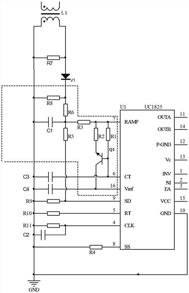
[0019] Such as figure 1 As shown, it is the voltage-current control mode automatic switching circuit according to the present invention, which includes a current transformer L1, a transistor Q1 and a chip U1.
[0020] The chip U1 adopts the current type pwm control chip, and the model of the chip U1 is UC1825.
[0021] The first output end of the current transformer L1 is sequentially connected to the first end of the resistor R7, the resistor R8, the capacitor C1, the capacitor C3, the capacitor C4, the resistor R9, the resistor R10 and the resistor R11 and grounded, and the second output end of the current transformer L1 is sequentially The second end of resistor R7, resistor R8, capacitor C1 and resistor R9 is connected, the second end of resistor R7 is connected with the anode of diode V1, the cathode of diode V1 is connected with the second end of resistor R8; th...
PUM
 Abstract
Description
Claims
Application Information
 - R&D
- Intellectual Property
- Life Sciences
- Materials
- Tech Scout
- Unparalleled Data Quality
- Higher Quality Content
- 60% Fewer Hallucinations
Browse by: Latest US Patents, China's latest patents, Technical Efficacy Thesaurus, Application Domain, Technology Topic, Popular Technical Reports.
© 2025 PatSnap. All rights reserved.Legal|Privacy policy|Modern Slavery Act Transparency Statement|Sitemap|About US| Contact US: help@patsnap.com