Underground optical communication system based on visible light communication

A technology of visible light communication and optical communication system, which is applied in the field of underground optical communication system, which can solve problems such as unreachable, soot blocking of lighting system, and easy interference of radio, so as to achieve the effect of safety supervision and safety improvement

Active Publication Date: 2020-09-08
SHENZHEN ADTEK TECH CO LTD
View PDF8 Cites 0 Cited by
  • Summary
  • Abstract
  • Description
  • Claims
  • Application Information

AI Technical Summary

Problems solved by technology

Due to the special environment of underground coal mines, most of them are roadway type and many coal mines are associated with other metal mines. The conventional radio is susceptible to interference and cannot achieve the conventional ideal effect, and the mine is an explosion-proof environment. The radio is transmitted in the form of electromagnetic waves and is easily placed at the antenna position. To gather energy, another explosion-proof mechanism is required, which is not conducive to underground use, and the form of cables can not only implement point-to-point communication, but also increases the cost and manpower of wiring construction
[0003] The mine is located underground and needs lighting for 24 hours. If the existing lighting facilities can be used for optical communication transmission and integrated with the audio and video monitoring system, it will be conducive to the implementation of underground safety production; System may be blocked by soot

Method used


Image

  • Underground optical communication system based on visible light communication
  • Underground optical communication system based on visible light communication
  • Underground optical communication system based on visible light communication

Examples


Embodiment 1

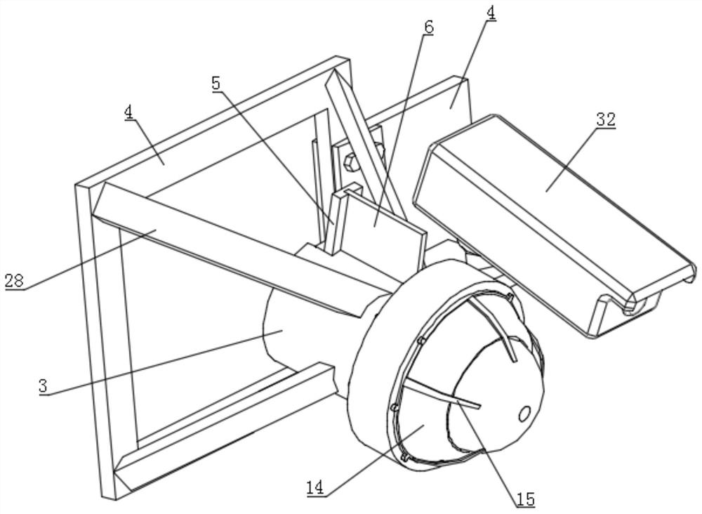
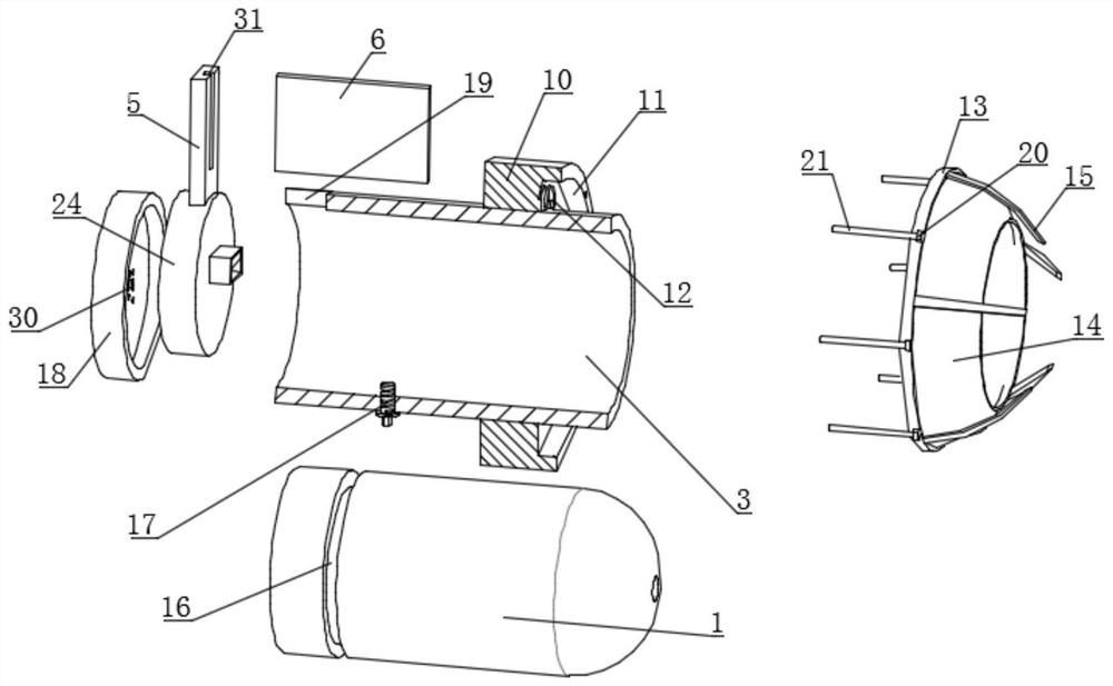
[0026] Embodiment 1. An underground optical communication system based on visible light communication, including a fixed light 1 and a camera 32, both of which are installed on the side wall of the mine via a mounting frame 4, and the fixed light 1 is installed in the inside of the installation sleeve 3, and the installation sleeve 3 is connected and installed on the side wall of the mine through the installation frame 4. A plurality of support rods 28 are fixedly connected on the side of the specific installation sleeve 3, and the support rods 28 are connected with the installation frame 4. Fixedly connected, the installation frame 4 is installed on the side wall of the mine through bolts, and the inside of the installation sleeve 3 is equipped with a controller 24 for processing signals. The inside of the controller 24 includes drivers, multiple amplifiers, and multiple modules. converter (A / D), a plurality of digital-to-analog converters (D / A), a microcontroller unit (MCU) a...

Embodiment 2

[0038] Embodiment 2. On the basis of Embodiment 1, downlink communication can be added to realize interactive communication. Specifically, the data server transmits the control command as a downlink communication through the nearest controller 24 to the A plurality of communication modules on the side wall of the mine, that is, the data server can send relevant instructions or information to each communication module located in the underground, such as allowing a certain camera 32 (there are many related existing technologies for related components that can even adjust the angle) The shooting angle and position change, voice and audio information are issued, announcements and precautions, alarms, etc., and the transmission process is that the data server transmits the data to the MCU of the communication module, and the data is loaded to the light source through the digital-to-analog converter, amplifier I, and the driver. It is transmitted, then received by the photoelectric r...

Embodiment 3

[0039] Embodiment 3. On the basis of Embodiment 2, in order to ensure that every worker in the mine can obtain relevant information in a timely manner, the system also includes a safety helmet for wearing on the individual, and the safety helmet is provided with a photoelectric receiver Board 6 and controller 24, the safety cap is connected to the installation block 7 through the feet 8, and there are threaded holes on the feet 8, so that the installation block 7 can be installed on the safety helmet by screws, and the controller is installed inside the installation block 7 24. The mounting block 7 is provided with a loudspeaker 30, and the mounting block 7 is fixedly connected to the connecting rod 9 connected to the photoelectric receiving plate 6, and the connecting rod 9 and the photoelectric receiving plate 6 on it are connected to the side of the safety helmet. In contact with each other, the helmet can support it and make it more stable. Similar to the above-mentioned da...


PUM


Abstract

The invention discloses an underground optical communication system based on visible light communication. The system comprises a fixed lamp and a camera which are both mounted on the side wall of a mine hole, a cleaning mechanism is arranged outside the fixed lamp; a controller is electrically connected with the fixed lamp and the photoelectric receiving plate; and the system further comprises a data server located at the ground position of the mine. The data server is electrically connected with the nearest controller; the data information communication module serves as uplink communication and transmits the uplink communication to the data server; the data server takes the control command as downlink communication and transmits the control command to the plurality of communication modules through the nearest controller to finish communication; the video monitoring and two-way communication can be achieved through an original lighting system, meanwhile, the cleaning mechanism with theexplosion-proof effect is further arranged, long-term stable operation of the system is facilitated, in addition, information can be transmitted to each individual, and therefore safety is improved,and the system is suitable for underground environment conditions.

Description

technical field [0001] The invention relates to the technical field of downhole safe operation, in particular to a downhole optical communication system based on visible light communication. Background technique [0002] Coal mines are widely distributed on the earth and are the most abundant and direct natural fuel resources in the world. Due to the particularity of their formation, they are non-renewable resources. Although the development of science and the emergence of many other energy sources are gradually replacing coal resources, but at present Coal still plays the role of an important resource in human activities. Most of the coal mines in the world are underground coal mines. With the continuous advancement of mining, the depth of mines continues to increase. The safety of coal mines has always been an important issue in mine production activities. How to strengthen safe production, improve early warning and post-accident handling is the key The top priority of ma...

Claims


Application Information

Patent Timeline
Patent Type & Authority Applications(China)
IPC IPC(8): H04B10/116H04N7/18H04N7/22B08B1/00
CPCB08B1/006H04B10/116H04N7/18H04N7/22
Inventor 沈宏岩
Owner SHENZHEN ADTEK TECH CO LTD
Why Eureka
Try Eureka