
Waste removing machine

A waste removal and racking technology, which is used in container manufacturing machinery, paper/cardboard containers, and box making operations, etc., can solve the problems of reduced production efficiency, scattered packaging boxes, etc., and achieve the effect of reducing labor intensity.

Inactive Publication Date: 2020-09-11
杭州鸿运彩印包装有限公司
View PDF10 Cites 0 Cited by
  • Summary
  • Abstract
  • Description
  • Claims
  • Application Information

AI Technical Summary

Problems solved by technology

[0005] The above-mentioned existing technical solutions have the following defects: when the remaining material is in the shape of the outer frame, if the cardboard waste removal device is used, the packaging box at the center of the cardboard can only be ejected, while the remaining material remains on the bottom plate, and the packaging box After being ejected, it is in a scattered state, and the staff needs to collect and organize the packaging boxes again, which reduces the production efficiency; if the claw wheel type waste stripping machine is used, because the remaining material is in the shape of a frame, the claw wheel type waste stripping machine is not easy The frame-shaped remaining material is torn and torn off from the packaging box, requiring staff to remove it manually, which reduces production efficiency

Method used


Image

  • Waste removing machine
  • Waste removing machine
  • Waste removing machine

Examples


Embodiment Construction

[0041] The present invention will be further described in detail below with reference to the accompanying drawings.

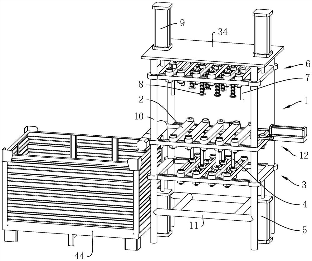
[0042] refer to figure 1 , which is a waste cleaning machine disclosed in the present invention, comprising a frame body 1, a plurality of bearing rods 2, a support frame 3, a plurality of ejector rods 4, a pushing cylinder 5, a fixing frame 6, a plurality of pressing rods 7, a plurality of Press block 8, fixed cylinder 9.

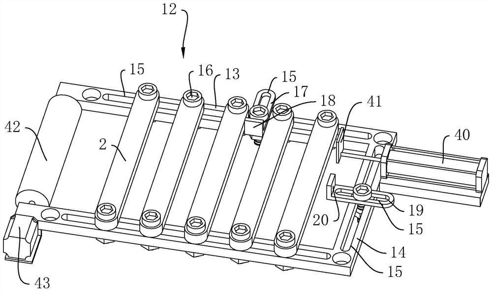
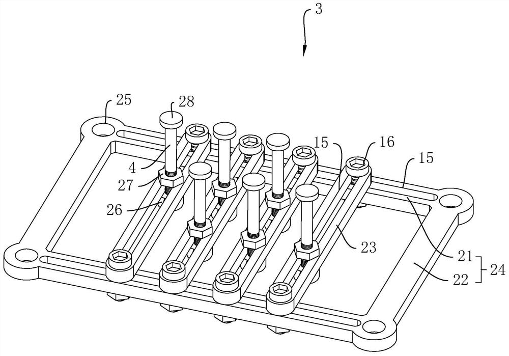
[0043] refer to figure 1 and figure 2 , the frame body 1 includes four uprights 10 and a connecting rod 11 for connecting the four uprights 10, the frame body 1 is fixedly connected to a carrier 12 at the middle position, and the carrier 12 includes two first cross bars 13 and a first A longitudinal rod 14, two first transverse rods 13 and one first longitudinal rod 14 enclose a U-shaped frame, and two first transverse rods 13 and one first longitudinal rod 14 are both provided with a vertical penetrating through rod 14. And the throug...


PUM


Abstract

The invention relates to the technical field of waste removing machines, in particular to a waste removing machine. The machine comprises a frame body, a plurality of bearing rods which are horizontally arranged on the frame body and arranged in the horizontal direction, a supporting frame which is slidably connected to the frame body in the vertical direction and located below the bearing rods, aplurality of ejector rods which are arranged at the top end of the supporting frame, pushing air cylinders which drive the supporting frame to move in the vertical direction, a fixing frame which isslidably connected to the frame body in the vertical direction and located above the bearing rods, a plurality of pressing rods which are arranged at the bottom end of the fixing frame, and fixing aircylinders which drive the fixing frame to move in the vertical direction. The machine has the effect that workers can conveniently remove excess materials on paperboards.

Description

technical field [0001] The invention relates to the technical field of waste cleaning machines, in particular to a waste cleaning machine. Background technique [0002] Carton is the most widely used packaging product, which is made of printed cardboard through the steps of die-cutting, waste removal, and box ordering (or box gluing). [0003] The structure of some existing cartons or cartons is relatively complicated, and the cardboard is relatively thin. When indenting, it is necessary to press out a number of residual material indentations in the middle of the cardboard. It is separate from the cardboard body model. [0004] In the prior art, when the cardboard is discarded, if the residual material on the cardboard is located at the center of the cardboard, a cardboard waste removal device is generally used to remove the residual material on the cardboard, which includes a top plate, a bottom plate, and a There are several pressing rods, and there are several through g...

Claims


Application Information

Patent Timeline
Patent Type & Authority Applications(China)
IPC IPC(8): B31B50/74
CPCB31B50/74
Inventor 童建林程国正
Owner 杭州鸿运彩印包装有限公司
Learn More