Assembly tool type truss superimposed sheet and construction method thereof

A laminated slab and tool-based technology, which is applied to floors, structural elements, building components, etc., can solve the problems of increased comprehensive manufacturing costs of laminated slab components, redundant floor reinforcement configuration transitions, and many support settings at the bottom of the slab, so as to reduce processing costs. and construction cost, not easy to deflect and deform, and convenient for construction

Pending Publication Date: 2020-09-11
山东高速德建集团有限公司
View PDF0 Cites 4 Cited by
  • Summary
  • Abstract
  • Description
  • Claims
  • Application Information

AI Technical Summary

Problems solved by technology

The shortcomings of traditional laminated slabs are low overall rigidity, poor bending resistance, easy cracking, large amount of steel bars, and more support settings at the bottom of the slab
After the concrete pouring is completed, all the steel bar trusses are buried in the concrete, resulting in transitional redundancy of the floor steel bar configuration, resulting in "waste" of steel bars, and resulting in an increase in the overall manufacturing cost of laminated slab components

Method used


Image

  • Assembly tool type truss superimposed sheet and construction method thereof
  • Assembly tool type truss superimposed sheet and construction method thereof
  • Assembly tool type truss superimposed sheet and construction method thereof

Examples


Embodiment 1

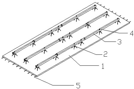
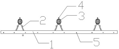
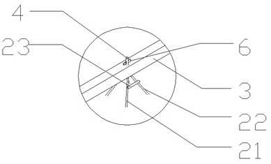
[0082] The present invention provides an assembled tool-type truss, wherein the shear steel bar support 2 is composed of a first bent steel bar 22, a second bent steel bar 21, a first flat bar 25, a second flat bar 24, and a connecting bar 23. The shape of the shear steel support is pyramid-shaped, and its main function is to connect the composite slab concrete and the assembled tool-type truss support beams into a whole to form a truss structure during the construction of the laminated layer on site, so that the laminated slab has the ability to bear the construction load during the pouring of concrete, The self-weight capacity of the structure and the rigidity guarantee are provided when the overall strength does not meet the design requirements.

[0083] A first flat rib extends outward from the beginning of the first bent steel bar, and a second flat rib extends outward from the beginning of the second bent steel bar.

[0084] The end of the first bent steel bar merges wit...

Embodiment 2

[0131] The main difference from Example 1 is that the structure of the truss support beam is a circular steel pipe, the bottom of the involved shear reinforcement support has a bottom plate, the bottom plate is provided with vertical and horizontal bottom bars, and the bottom bars in the long side direction are non-prestressed bars. The short side direction is non-prestressed reinforcement, and the shear reinforcement support is tied to the vertical and horizontal bottom reinforcement.


PUM

PropertyMeasurementUnit
Diameteraaaaaaaaaa
Thicknessaaaaaaaaaa

Abstract

The invention relates to an assembly tool type truss superimposed sheet and a construction method thereof. An assembly tool type truss is included. The assembly tool type truss further comprises an anti-shear reinforcement bracket and truss support beams, wherein the anti-shear reinforcement bracket is pyramid-shaped. The truss support beams in the assembly tool type truss are of tool type assembly structures; round holes are provided at the junction of the truss support beams and the anti-shear reinforcement bracket; the truss support beams are arranged in a segmented manner; and the truss support beams are connected in an socket-and-spigot manner. The construction method of the assembly tool type truss superimposed sheet comprises the steps of manufacturing the anti-shear reinforcement bracket, T-shaped connection portions, the truss support beams and a base plate in sequence; connecting and combining the anti-shear reinforcement bracket and the truss support beams; paving anti-shearreinforcement bracket and truss support beam combined members on horizontal and vertical reinforcements; conducting concrete pouring of prestressed superimposed sheets; mounting prestressed superimposed sheets; pouring a second layer of superimposed concrete; and disassembling the truss support beams.

Description

technical field [0001] The invention belongs to the technical field of construction, and in particular relates to an assembly tool type truss laminated board, which is a support-free laminated board. Background technique [0002] Traditional laminated slab components often used in the construction field can reduce wet work steps and construction formwork in the construction process and improve construction efficiency. The disadvantages of traditional laminated slabs are low overall rigidity, poor bending resistance, easy cracking, large amount of steel bars, and many support settings at the bottom of the slab. The traditional steel truss laminated plate structure produces large deflection and deformation during the hoisting process, and even causes the base plate to crack. During the construction of the laminated layer, a large number of supports must be provided at the bottom of the slab to increase the overall vertical bearing capacity of the laminated slab, reduce the de...

Claims


Application Information

Patent Timeline
IPC IPC(8): E04B5/38E04C5/06
CPCE04B5/38E04C5/0627E04C5/0656
Inventor 于静胡兆文杨玉桐
Owner 山东高速德建集团有限公司
Why Eureka
Try Eureka