Self-disinfection draught fan and fan with disinfection function

A fan and fan technology, applied in the field of fans with disinfection function, can solve problems such as air flow resistance, and achieve the effects of smooth air intake, wide application range and simplified structure

Pending Publication Date: 2020-09-11
中山信科智能电器制造有限公司
View PDF1 Cites 0 Cited by
  • Summary
  • Abstract
  • Description
  • Claims
  • Application Information

AI Technical Summary

Problems solved by technology

[0005] However, the existing equipment is to add disinfection and sterilization devices directly on the passage of its gas flow, and the structure of directly adding disinfection and sterilization devices on the passage will produce more obvious resistance to the flow of air.

Method used


Image

  • Self-disinfection draught fan and fan with disinfection function
  • Self-disinfection draught fan and fan with disinfection function
  • Self-disinfection draught fan and fan with disinfection function

Examples


Embodiment 1

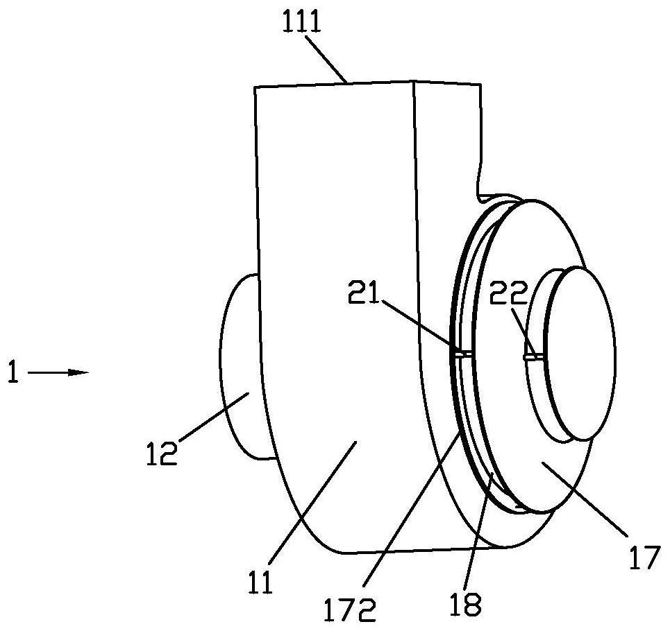
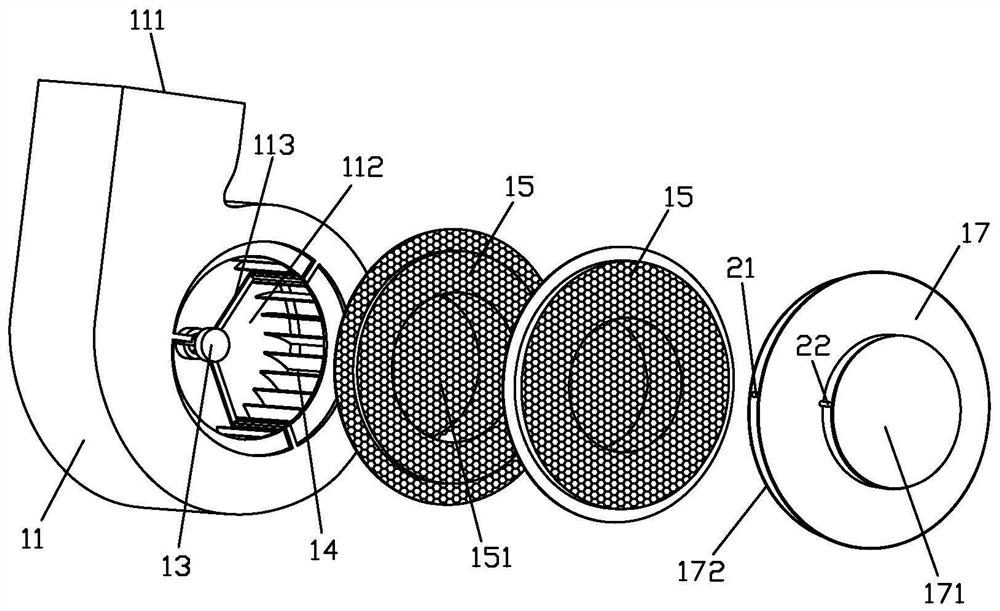
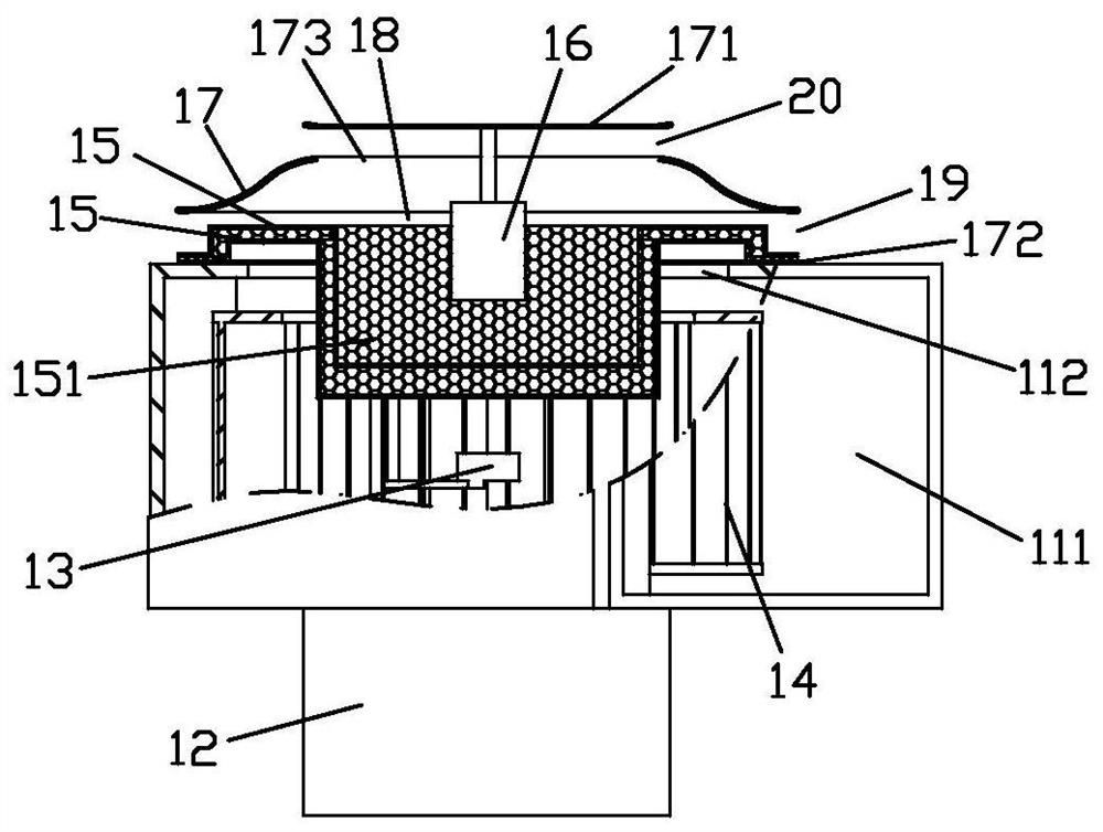
[0034] Such as Figure 1 to Figure 3 Shown is the self-sterilizing fan 1 of Embodiment 1, which is a centrifugal fan, which includes a casing 11 , a motor 12 and an impeller 14 .

[0035] The casing 11 is provided with an air inlet 112 and an air outlet 111, the air inlet 112 is located on the front of the casing 11, the air outlet 111 is located at the upper end of the casing 11, the impeller 14 is installed in the casing 11, and the motor 12 is installed in the casing 11 On the back side, the output shaft of the motor 12 is connected with the impeller 14. In order to enable the fan itself to have a disinfection function, a disinfection component is integrated at the air inlet of the casing in this embodiment.

[0036] Wherein, the disinfection assembly includes a shroud 17, an ultraviolet lamp and two layers of photocatalyst nets 15, and the number of layers of the photocatalyst net 15 and the quantity of ultraviolet lamps can be determined according to disinfection require...

Embodiment 2

[0049] The difference between the fan with disinfection function of Embodiment 2 and Embodiment 1 is that a disinfection device is added in the form of a branch circuit. This disinfection device is a combined labyrinth gas-liquid disinfection device disclosed in Chinese Patent No. 200610035126.8. .

[0050] Such as Figure 5 As shown, the disinfection and sterilization device is installed in the fan housing 2, positioned above the self-disinfection fan 1, and the fan housing 2 is provided with a branch air inlet 24 corresponding to the air inlet of the disinfection and sterilization device, and the air outlet of the disinfection and sterilization device The end is provided with an air duct 4, and the air duct extends into the first side air outlet 19, thereby connecting the air outlet end of the disinfection and sterilization device with the air inlet space 18. The inlet of the combined labyrinth gas-liquid disinfection and sterilization device 3 is the air inlet end, and the...


PUM


Abstract

The invention discloses a self-disinfection draught fan. The self-disinfection draught fan comprises a machine case, a motor and an impeller. The machine case is provided with an air inlet and an airoutlet. A disinfection assembly is integrated at the air inlet of the machine case. The disinfection assembly comprises a flow guide cover, an ultraviolet lamp and at least one layer of photocatalystnet. The flow guide cover is fixed to the air inlet of the machine case. An air inlet space is formed between the flow guide cover and the machine case. The ultraviolet lamp and the photocatalyst netsare arranged in the air inlet space. The photocatalyst nets cover the air inlet. The disinfection structure is integrated on the self-disinfection draught fan, and the self-disinfection draught fan has the disinfection function and is smooth in air inlet. The invention further discloses a fan with the disinfection function. The fan comprises a fan shell and the self-disinfection draught fan. Thefan shell is provided with a suction port and a blowing port. The fan shell is internally provided with an air guide channel. The self-disinfection draught fan is mounted on the suction port. The self-disinfection draught fan sucks air form the suction port. The air guide channel is connected with the air outlet and the blowing port of the self-disinfection draught fan. In the using process of thefan, the air flows smoothly.

Description

technical field [0001] The invention relates to a self-sterilizing fan, and also relates to a fan with a disinfecting function. Background technique [0002] The fan is a machine that relies on the input mechanical energy to increase the gas pressure and discharge the gas. It is a driven fluid machine. Fans are widely used in buildings, factories and other spaces to achieve ventilation and cooling. For example, vertical fans in households use fans to drive gas flow, and fans are also used in factory ventilation systems to drive gas flow. [0003] With the improvement of living standards, people have higher and higher requirements for environmental sanitation. In order to disinfect and sterilize the environment, they will choose to purchase an additional air sterilizer, and additional purchase of an air sterilizer will undoubtedly increase the cost and increase the share. land area. [0004] In order to sterilize the air without purchasing an air sterilizer, there have been...

Claims


Application Information

Patent Timeline
Patent Type & Authority Applications(China)
IPC IPC(8): F04D17/16F04D25/08F04D29/42F04D29/44F04D29/00A61L9/20F04D29/40
CPCA61L9/205F04D17/16F04D25/08F04D29/002F04D29/403F04D29/4233F04D29/441
Inventor 陈亮言李显恩
Owner 中山信科智能电器制造有限公司
Why Eureka
Try Eureka